30N06L, not 30N60L.
This is a 'logic level' FET. The drive circuit doesn't have enough voltage to properly drive a standard FET. You may be able to use something like a 3205 for testing to see if there are other problems but you'll need to get the proper transistor for long term use.
This is a 'logic level' FET. The drive circuit doesn't have enough voltage to properly drive a standard FET. You may be able to use something like a 3205 for testing to see if there are other problems but you'll need to get the proper transistor for long term use.
Ok i orderd the Correct transistor.. (FQP30N06L)
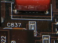
The 47 ohm resistor connected to Leg 1 of that transistor both of the pads burnt off the board...
Instead of an SMD resistor going back in that location I was gonna use a leaded resistor to i can solder right to leg 1 and the other side i can drill a small hole thru the board and solder it from the under side of the board..
Would a 1/4 watt 47 ohm resistor work or should i use a 1/2 watt ?
Also the 0.1 ohm resistor is a 2 watt ??
3rd question is With the FQP30N06L , 0.1 ohm and the 47 ohm resistor all being bad would that cause the low ohms light ?
A 1/8w resistor would be sufficient. A 1/4w will work.
I'd suggest that you solder to the pad and fix the resistor down with a suitable fixative/adhesive. I think these are only 2-layer boards but I'm not sure. Unless you can see light all around the pad and there is no trace/copper on the other side, it's not safe to drill.
Match the size when ordering.
I can't help with the 3rd question. I've never had an amp with this failure that I looked at the LEDs.
Yes this is a double sided board..
Both pads are missing..
I can drill thru the board on 1 side of the resistor and connect it from underneath the board and the connect the other side of the resistor to Leg 1 from the top side of the board and use some silicone to keep the resistor in place..
I guess i wait til friday or saturday to test this amp somemore since thats when the parts come in..
- Status
- This old topic is closed. If you want to reopen this topic, contact a moderator using the "Report Post" button.
- Home
- General Interest
- Car Audio
- JL Audio 1000/1