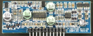
Ok got the parts today and made the repairs to the audio driver board. Installed everything and put the amp in the sink and clamped it down.
The amp powers up and idles fine. It has +/- supply voltage to all of the op-amps, it is producing +/- rail voltage, everything seems to be good.
There is no audio........I think the little black relay is suppose to "click" when the amp is powered but its not. Sending a 100Hz sine wave to the amp with the scope set at 2ms/5vd when I increase the volume all I hear is a LOUD buzzing noise from the board which I think is coming from that relay but not sure.
I see no audio on the scope. There is no DC on the output terminals.
Am I missing something??? Not sure whats going on here????
It's switched through a group of components. Q5 is what drives it but the amp could be in protect. Checking the points that I listed will tell you if the amp is working properly otherwise. If so, you troubleshoot the drive circuit for the relay. If there is a problem with the amp's audio circuit, you troubleshoot that. When the audio is working properly, the relay may engage.
I didn't look at the entire circuit previously.
Look at the DC voltage on transistors Q3, 4 and 5 on the PS driver board. Those should tell you why the relay isn't engaging.
I have rail-rail oscillation on one terminal of each inductor and audio on the other terminal of each inductor.
Not sure if I can get to all the test points on the transistors you want me to check but I will try, its very tight in there alot in the way.
What are Q3, Q4, and Q5 and whats there purpose?
These transistors are marked BR and the only thing I have found is MSB1218A is this correct? They are 45 volt pnp or is there another part number?? Just trying to make sure when I give you the readings I use the right pin configuration the MSB1218A is the same as a 3904 and 3906.
Q3 2SB1269
C: .960 vdc
B: .003 vdc
E: .488 vdc
Q4 MSB1218A
C: 14.12 vdc
B: .924 vdc
E: .546 vdc
Q5 MSB1218A
C: 14.13 vdc
B: .544 vdc
E: .026 vdc
Q6 MSB1218A
C: 4.95 vdc
B: .083 vdc
E: .058 vdc
C3 47uf 16v aluminum cap
+ .917 vdc
- .005 vdc
I think its obvious that C3 is not charging up and turning on Q4 and Q5 to connect the relay ground as you stated. So thats why the audio is not being connected to the speaker terminals.
You also stated that C3 is charged through R5, so if C3 is not charging R5 could be open or defective??
- Status
- This old topic is closed. If you want to reopen this topic, contact a moderator using the "Report Post" button.
- Home
- General Interest
- Car Audio
- Hifonics Brutus BX 2005d
