Hi i have another PPi A600.2 Black series amp #2. I did the same thing power it up with rca cable and speakers But the power light and the low ohms light are both lit together, the sound sounds disturted, and i know the low ohms light isn't suppost to be lit all the time only with u are using low ohms i have two mtx 8 ohms a piece set to 4ohms. even with i unplug the speakers off the channels the light is still on both was wondering if i can get some help on this amp thank you for ur time
The low ohms led is the give away that that amp has blown outputs in one or both channels. Its the common symptom of the low ohm led to light up when outputs are shorted. Also look for the 10 ohm resistors behind the RCAs to be open.
I just completed a dozen of these amps for a client/friend, so I am very familiar with them currently as he wanted his collection completely restored to like new operation.")
I just completed a dozen of these amps for a client/friend, so I am very familiar with them currently as he wanted his collection completely restored to like new operation.
Only the SIP channel driver modules are tough to come by. And maybe the gain pots, but they can be cleaned. The SIP modules are those ceramic cards standing upright in the middle of the amp. Once physically damaged they are somewhat impossible to repair. I.E. if you lift one of the trace tabs it will never take solder again, and a wire around will have to be done, if possible.
Usually they need a touch up of all the solder joints in some cases this brings them back to life. If your not use to soldering then don't try it, as too much heat plays havoc with the substrates and cause de-lamination to occur. Try it later on when your more confident about your soldering skills.
The other failures are the 100 ohm resistors under the larger SMD transistors blowing open. Perry has a tutorial on how to work around that issue < good stuff his web site>, you might try to look into it before you jump head long into trying to repair these amps by yourself or with help from any of us here.
Just click on the links below any of Perry Babin's posts. His web site is the best training I believe, and your going to need his basics just to get by inside of these or any amp out there...Check his links out as soon as you can. It will brace you for whats coming next.
Sorry guys it tooked me awhile to post pix of ppi A600.2
Hi guys sorry it tooked a while to post a pix of the amp. This is the first amp that has power and low ohms light both lit up. in the pix i found R57 is open not on the board will that cause sound problems here are a few pix i would like to know what to test and what i should do next thank you
Hi guys sorry it tooked a while to post a pix of the amp. This is the first amp that has power and low ohms light both lit up. in the pix i found R57 is open not on the board will that cause sound problems here are a few pix i would like to know what to test and what i should do next thank you
Attachments
We are always here so no biggy
Now I see you posted the same pics for both threads so your gonna need to differentiate between the two amps and repost pics of the correct amp in which ever thread they need to be changed.
You see the same pics in both threads causes confusion because a lot of the visual information is incorrect for one of these amps.
I am taking it that these pics are the ones for this thread description so I am posting in this thread for now.
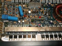
1: I see a 10 ohm current limit resistor loose up front. This melted its solder and fell off the board just behind one of the RCAs. This is a good sign of which channel is damaged as when these amps blow outputs they tend to load a high amount of current thru that resistor back onto the RCA shield ground back to the HU. They often just blow open, but in this case it appears to have melted its solder and allowed the resistor to fall out of circuit. I am 99.99% sure this channel has blown outputs, or its passing huge amounts of DC voltage out of it due to some failure related reason.
Based on your description of the leds operation I would ohm meter the outputs for this channel. It's likely that only one or two are bad but due to the parallel design I would replace the entire set with as closely matched as possible new ones. The center two transistors < B1058A and D1562A > are drivers and they can also be damaged if the outputs failed.
Replace the resistor with new, and replace any damaged outputs and drivers in that channel.
Have you studied up on Perry's web-site yet? On his web site it will show you how to meter these devices and it will show you the acceptable meter readings for a GO- No Go test with a meter for these devices.
2: up under the big metal ground buss bar the very last resistor is part of a output zobel filter for that channel. it could be damaged < I.E. burnt or blown open > from the channel failure. It can not be seen in the pics you posted but I have done too many of these to overlook it as possibly failed due to excessive voltage on the speaker terminals. its failure is always linked to number 1 above.
You should look at this and test it to make sure its like its mate near by closer to the speaker terminals < one for each channel, the suspect is hidden under the bar > Replace as needed.
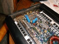
3: I also see a fair amount of water damaged on this amp < corrosion and silt build up etc..> This will have to scrubbed off somehow. I recommend a paint brush with semi stiff bristles and some cleaner like pure alcohol or PC Board cleaner you can buy at the electronics store. not the alcohol you buy from a pharmacy labelled as rubbing alcohol as it contains 30% fragrance and moisturizers to prevent sink irritation. < this stuff is no good on electronics so you don't want to use it. You can use denatured alcohol from a hardware store found in the paint section if you like. It quality is ok to use in this case.
please check the pics in the other thread and make sure they are for that description of failure for me thanks
Now I see you posted the same pics for both threads so your gonna need to differentiate between the two amps and repost pics of the correct amp in which ever thread they need to be changed.
You see the same pics in both threads causes confusion because a lot of the visual information is incorrect for one of these amps.
I am taking it that these pics are the ones for this thread description so I am posting in this thread for now.
1: I see a 10 ohm current limit resistor loose up front. This melted its solder and fell off the board just behind one of the RCAs. This is a good sign of which channel is damaged as when these amps blow outputs they tend to load a high amount of current thru that resistor back onto the RCA shield ground back to the HU. They often just blow open, but in this case it appears to have melted its solder and allowed the resistor to fall out of circuit. I am 99.99% sure this channel has blown outputs, or its passing huge amounts of DC voltage out of it due to some failure related reason.
Based on your description of the leds operation I would ohm meter the outputs for this channel. It's likely that only one or two are bad but due to the parallel design I would replace the entire set with as closely matched as possible new ones. The center two transistors < B1058A and D1562A > are drivers and they can also be damaged if the outputs failed.
Replace the resistor with new, and replace any damaged outputs and drivers in that channel.
Have you studied up on Perry's web-site yet? On his web site it will show you how to meter these devices and it will show you the acceptable meter readings for a GO- No Go test with a meter for these devices.
2: up under the big metal ground buss bar the very last resistor is part of a output zobel filter for that channel. it could be damaged < I.E. burnt or blown open > from the channel failure. It can not be seen in the pics you posted but I have done too many of these to overlook it as possibly failed due to excessive voltage on the speaker terminals. its failure is always linked to number 1 above.
You should look at this and test it to make sure its like its mate near by closer to the speaker terminals < one for each channel, the suspect is hidden under the bar > Replace as needed.
3: I also see a fair amount of water damaged on this amp < corrosion and silt build up etc..> This will have to scrubbed off somehow. I recommend a paint brush with semi stiff bristles and some cleaner like pure alcohol or PC Board cleaner you can buy at the electronics store. not the alcohol you buy from a pharmacy labelled as rubbing alcohol as it contains 30% fragrance and moisturizers to prevent sink irritation. < this stuff is no good on electronics so you don't want to use it. You can use denatured alcohol from a hardware store found in the paint section if you like. It quality is ok to use in this case.
please check the pics in the other thread and make sure they are for that description of failure for me thanks
Ok what part of northern cali u from? if u dont mind me asking and are u talking about the R57 resister that is loose or the one by the case of the corner? and i will need help on how to test these parts thank you On both post i posted the same amp i figure i will work on the one that Has both LED lights on with power and low ohms light and once i figure out this one it will be more easier for me to trouble shoot the other amp
Retired I now live in central Cali a bit east of Monterey Ca.
I was speaking about that loose resistor and its brother located just behind the RCAs, that is where that resistor went before it melted its solder joints and left for higher ground lol..
They are 10 ohm 2 watt ceramic metal film resistors and they are available off ebay for cheap. Resistors are so cheap you really don't have to worry about clones and the such, so ebay is a safe place to buy them for the most part.
The other resistor in question in the one just at the end of that big ground bar and just underneath it near where the bar is soldered to the board. I have seen them burn up when a channel fails. if it shows no signs of heat stress and it reads like its match just to the right of the speaker terminals then your all good on that one. I would replace the ones behind the RCAs and the one floating. They burn up somewhat regularly and I even stock them just because of their high failure rate.
so are u talking about FB1 resister and right behind U3 rca that blue resister i should test or replace sorry maybe u can draw a arrow to show me on the pix ? lol cool yea i live by chico cali been wanting to learn hands on working on amps, and my next thing is i dont really have a good solder gun either so i need some help on which stuff i should get for soldering stuff on amps. Thank you again
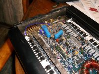
please see attached pic it has been marked up to show where the loose resistor went, and they both look burnt. 10 ohm 2 watt.
also you will see another resistor has been circled its also desoldered and likely burnt, and a small arrow points to it sister for the other channel under the bar and it also is likely damaged. These are the zobel output filters and they overheat when a amp is clipped badly and or it has some out of bandwidth output on the speaker terminals.
These device die due to abuse of the amp, and are side effects of the amps failure mode so fixing these items will not completely fix the amp. they are just symptoms of a greater issue lurking elsewhere in the amp channels.
Attachments
ok so should i test the resister to see if there still good? if not where can i get them? and u mention the other ones with 3 leg post should i messure them to see if those are good too? and if not where to get those parts? and the one under the bar lmao how to i get that one out lol to test it or replace it thank you again
Perry I am borrowing your links hope its ok, and thanks
Superjoey01 please click on any of these links below except for the computer link for some excellent reading that you need to do before you proceed with any repair work on your amps.
Links >> Basic Car Audio Amp Repair --- Basic Car Audio Electronics --- Basic Transistor Testing --- Basic Switching Power Supply Design --- Basic Computer Skills << Links
Perry's web site will answer many of your typical questions your asking now, and it will save loads of forum thread space if you study up a bit..... His training site will give you the head start you are looking for and its free and well designed so that you can take things at your own speed. Please brief yourself for this service work as its going to get a lot deeper and you really need to know the info Perry has put together for you.
I am detecting from your questions that your not ready to do this sort of repair yet. With some small training from Perry's site you will be ready to undertake this repair. I send you there to save both of us bunches of time and effort. I can guide you quickly if you have some rudimentary understanding level of what your working with.
I have done enough of these to guide a blind man, but the blind man needs to know what he is fumbling around with. Perry's site is your best bet to garner the little details you need to start this job....
I like many others here want to help you but you must help yourself also. And the info on Perry's web site will brace you some for whats next to come. Repairing electronics is not as simple as just replacing the visually bad components and you really need to know how to use the tools of the trade and some of the ins and outs before you run head long into this project. Your learning curve is the bottle neck to getting this done quickly. Perry's web site will smooth a lot of this out and help you vastly to achieve the results your looking for in this project.
I am not trying to be mean spirited towards you in any way. I am trying to guide you correctly to the help you need in the sequence you need it so you can be successful with your efforts. So please don't take any of my guidance harshly as its the best way for you to go, and we all want the best for you and your project here on the DIY...
Were here on the DIY not going anywhere so we will all be here after you have done some study up. Take a break, read some and then decide if this is for you or not and we will all be here when you have a better idea of what your into...
Last edited:
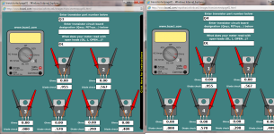
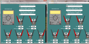
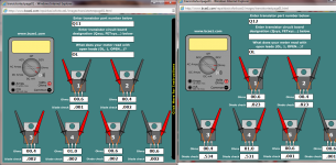
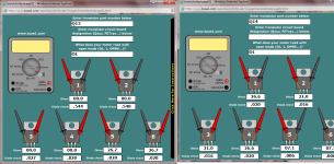
Got some of the transister on the side of the amp tested
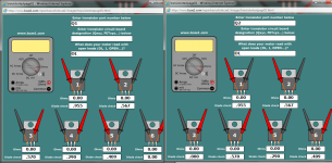
Hi guys i got some of the transister tested only have Q1 to Q6 tested so far i'm working on the rest of them thank you Joey
Hi guys i got some of the transister tested only have Q1 to Q6 tested so far i'm working on the rest of them thank you Joey
Attachments
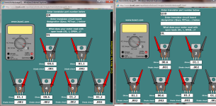
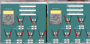
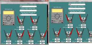
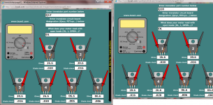
hey guys i finally got one side of the amp transister done
hi guys i just now got the one side of amp done testing the Transister here are the rest thank you for ur help and i been reading a bit on perry site it helps alot takes me a bit to learn but willing to try from Joey
hi guys i just now got the one side of amp done testing the Transister here are the rest thank you for ur help and i been reading a bit on perry site it helps alot takes me a bit to learn but willing to try from Joey
Attachments
- Status
- This old topic is closed. If you want to reopen this topic, contact a moderator using the "Report Post" button.
- Home
- General Interest
- Car Audio
- PPi A600.2 #2 Powers up but with both lights on