Hi all. First post here. I was told over at diyma to post about my amp over here, so here it goes.
I got my old Opti Drive Plus 100 from a buddy a few weeks back. This was mine back in HS. I powered it up and saw that it starts out in protection mode for a couple seconds, comes out of protection mode for a couple seconds, and goes back into protection mode again. It does this with nothing connected. If I hook it up to speakers and an audio source it plays loud and clean for those 2 seconds it is not in protection. It won't come out of protection mode the first time I connect it to a power source. Only every time after. A good Opti Drive will go green immediately no matter what.
So..I decided to take it upon my novice self to figure this out.
I remembered that back in the day a couple diodes in the power supply section got hot and unsoldered themselves from the board. I soldered them back in and did not have an issue after that. I went ahead and pulled them to check them. They are fine.
The big caps in the power supply had scorch marks on them from my solfering iron (I was a teenager when I did that). I replaced them. No luck. While checking continuity I noticed that the ground side on one of the biggest caps was not connecting to the trace, which was common ground. After a couple attempts to fix this, I ended up just running a lead from the cap to the ground to see if that was it. Nope.
I pulled the mosfets off the board and checked them. One had leads that were about to break and another would keep losing resistance when I checked the closed circuit after closing the gate. I bought new mosfets and that did not help.
I pulled the output transistors and checked them too. They all test out identically.
There are no scorch marks on this board.
I tested all the little caps on the board and they all seem to at least be functional. None are shorted or open.
My next step was going to be to replace all the little caps hoping that one is dried out and cannot hold a charge. Am I heading in the right direction, or am I missing something?
Whats the DC voltage on each set of speaker terminals when its out of protection?
I would connect a DC volt meter to each channel one at a time and see what DC output the amp makes when it drops out of protection on fire up. Above a certain level the protection circuitry will re-trigger, so I would check that next.
Also I remember these amps suffering from opto-coupler failues so I would check those and the associated circuitry driving them. These amps were called OPTI drives because they used opto-couplers to completely decouple the audio side from the 12 volt side like PG and others did back then, so as to prevent ground loop noise issues. hope this helps some...")
I would connect a DC volt meter to each channel one at a time and see what DC output the amp makes when it drops out of protection on fire up. Above a certain level the protection circuitry will re-trigger, so I would check that next.
Also I remember these amps suffering from opto-coupler failues so I would check those and the associated circuitry driving them. These amps were called OPTI drives because they used opto-couplers to completely decouple the audio side from the 12 volt side like PG and others did back then, so as to prevent ground loop noise issues. hope this helps some...
The circuit boards on these amplifiers are VERY easy to damage. I wouldn't recommend only removing parts when you absolutely have to. It's possible to damage the vias that connect the top traces to the bottom pads. If they are damaged, when you reinstall the parts, you may not have a good connection to the trace on top and that can make the amp very difficult to troubleshoot/repair.
Ok, dumb question. What are the opto couplers? I will check for dc voltage on the channels and report back in a few days.
Thanks for the advice on the board. I have checked all the traces on everything I have replaced so far. I can see how the pads can come off with too much heat.
Thanks for the advice on the board. I have checked all the traces on everything I have replaced so far. I can see how the pads can come off with too much heat.
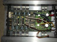
Your pic blurs up when I blow it up to full screen but look at the center of the amp for the 6 legged devices black in color rectangular in shape. I see two at least and a possible third under the brown wire unless that's a voltage comparator which is common to this design.
If either of those opto-couplers are not working or they have bad signals from the amp your amp will drop offline into protect mode. not much other can do that on this amp since these represent the decoupled feedback from the amp back to the power supply to shut down or stay online..Really simple after you see a free hundred of this basic design. lots of name brand amps do this exact same thing. lanzar decided to use it as marketing and a product name...
And Perry is very much correct about the PCB being damaged easily you might have to hard wire thru the hole to correct for such issues if they happen...hope this helps some
Your pic blurs up when I blow it up to full screen but look at the center of the amp for the 6 legged devices black in color rectangular in shape. I see two at least and a possible third under the brown wire unless that's a voltage comparator which is common to this design.
The one under the brown wire is 8 legged and different from the other 2. Those are actually 5 legged. They look like they are supposed to be that way. The same leg is missing frm both and it appears that the spot on the board where the missing leg would connect to goes nowhere. There are no marks that would lead me to believe that they were burned off. I will get out the multimeter tomorrow and check DC volts on the channels as well as verify that there are in fact no traces coming off the solder points where the missing legs are.
What amount of DC voltage would be an issue and do I test with or without an input source? I'm assuming it doesn't matter since it goes into protection with nothing connected.
Adding to this. Those are 4N25 Octocouplers. Pin 3 has no connection, so the fact that it is missing on these is ok. So, based on the link below that diagrams these out, how do I test these?
Learning to Use an Optocoupler or Optoisolator
Learning to Use an Optocoupler or Optoisolator
Adding to this. Those are 4N25 Octocouplers. Pin 3 has no connection, so the fact that it is missing on these is ok. So, based on the link below that diagrams these out, how do I test these?
Learning to Use an Optocoupler or Optoisolator
I would have checked for DC offset on the outputs first. Have you looked for any DC on the speaker terminals of the amp yet? No RCAs and no Speakers connected turn on the amp and use a meter to read any DC voltage on the speaker terminals. Let me know what you find there first.
Then i worry about the opto's being functional. The link you sent shows the basic operation of them so it should be simple to check the output of the opto to see if its giving you proper output . You will have to track down where each opto connects to the PWM chip to decide weather or not the signal is correct for that pin.
Those opto's are the usual culprits when one of these amps is not latching online. but you must also check the things that the opto's are connected to also to make sure they are not just being tripped by some over looked symptom.
They may be 100% functional and doing there job correctly due to uneven rail supply, DC offset on the speaker terminals, uneven lower rails, etc....
Are you sure its 2.5 volts DC? or could it be 2.5 Milli-volts DC? what range is your meter on ?
In most amps the DC offset out will trigger the amp to shut down at much lower levels somewhere between 50 and 300 milli-volts DC in many designs.
At 2.5 volts DC out your amp will fry voice coils in many circumstances and that level might increase with audio drive levels. So I am thinking your opto's are just fine and that there are some issues with both channels producing that level of DC output.
A new amp will likely being the 0 to 5 milli-volt range, a used amp in the 5 to 15 milli-volt range. Many manufactures recommend 15 milli-volts or less DC offset on the speaker terminals on rebuilds and less on new unused gear.
Well, I thought I had it sitting at 20v range for DC. If I put it in 2000mv range and it would go out of range. I have a crappy Centech multimeter, so maybe it was reading wrong. I will see if I can borrow a good one and try again. I connected this thing to some old speakers that I don't care about and they played just fine. I was assuming that alot of DC voltage would cause the speakers to pop loudly and eventually fry. Maybe not?
So if I really have that much DC hitting the speaker terminals, where do I go now?
So if I really have that much DC hitting the speaker terminals, where do I go now?
High DC offsets are usually caused by damaged transistors that are leaking and drifting with thermal heat build up. I start with the input pairs myself but it could be any of the transistors in the main amp stage. Each main amp has a DC blocking input capacitor. The purpose of that cap is to block DC from the preamp buffer input of the amp< the IC's near the RCAs>. So it is doubtful that the DC problem could be anywhere else but in the main amp sections.
Amps that are driven into clipping hard all the time seem to have damage of the input transistor pairs by my experience, and when the damage is not there its usually in the next stage of the amp. outputs and drivers can be the source of the issue but they tend to fail outright and short most of the time and are easily found by using a meter on its low ohms range. Using a ohm meter to find leaky transistors is a needle in a haystack situation IMHO. In this case your going to have to disable the protection opto somehow so the amp will stay on long enough for you to trouble shoot the main amp stage. lifting the input to the opto on the audio side might disable the protection so the amp will stay online for you to tech it out.
If time is a factor and you are limited in training on this sort of work you might just want to just replace the input pairs of each channel with new devices and then recheck your amps output DC. They are usually jelly bean transistors costing 3 cents each in bulk, so depending on the input configuration your looking at 12 to 24 cents to replace all of those transistors with new ones and not worry about the possible leakage issues. retail prices of those transistors will likely be much higher but I have only bought in bulk so I only know wholesale bulk pricing.
Have you looked into Perry's training web-site ? just look under any of his posts including in this thread and you will see links to click on. Perry's site is the best info on the web, period ! I suggest you look into his training info to see where this amp repair is likely headed. He has tons of info there and he might also have some info on this series of Lanzar amp. For now though please recheck the DC output of the amp first...
Since I am a complete novice to this I don't mind throwing some new parts on it and see what happens. I have already replaced the caps on the power supply section and the mosfets as well.
Are you talking about replacing the tiny cylindrical transistors on the board that live in the center secion? I will get some full res pics up later tonight of my amp.
I'm going to borrow my friend's fluke tonight and check for DC voltage again. I think my meter was acting up on me. I was reading about having DC bleed into the speaker terminals and fro what I've read I should be getting a loud pop and of course will most likely damage my speakers. This one comes on and plays just fine for that short period.
I've checked out Perry's website and it is helpful, however still a little over my head. I have to say I am having fun trying to learn as I go. Thank you so much for all the fantastic advice. Although it would have probably been more wise to pay a professional to repair this amp, I'm still glad that I'm going through the process of trying to learn this. I've thrown away some really nice amps in the past that may have just required a few bucks worth ofparts and some knowledge to get back up and running.
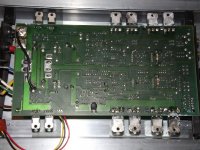
Alright. Looks like my meter had a low battery and was giving off funky voltage readings. It appears like I get around 250-300mv for a moment and then it drops down to 15-20mv before it goes into protection. After it goes into protection DC volts come back up to around 250mv and slowly drop off. I noticed that when it goes out of protection I hear a faint click sound on the board. I can't tell where it is coming from other than possibly somewhere in the power supply section or maybe towards the middle. I'm thinking that maybe I should get this over to someone else to figure it out. I reposted the pics below. They come out a bit better.
Last edited:
An externally hosted image should be here but it was not working when we last tested it.
An externally hosted image should be here but it was not working when we last tested it.
One of those opto's should be connected to a small signal transistor located on each channels output. That transistor should be the offset trigger for the opto to inhibit the amps power supply.
The other opto is likely used to detect balanced rail supply, and if it is not satisfied that both rails are present and balanced it also inhibits the power supply.
The readings your getting sound OK as all amps have some sort of turn on output that settles to normal conditions. Could you measure the plus and minus power supply voltages while doing this turn on test again? if the rails are not correct and balanced this could also cause the power supply to inhibit.
The input pairs are located in the center of your picture just behind the op-amps chips. but check the rail supply before you do anymore component removals, and let me know what voltages you get with your negative probe lead connected to the RCA shield or the center tap ground of the power supply toroid transformer, both should be the same reference level for the black lead of your meter.
The input pairs are located in the center of your picture just behind the op-amps chips. but check the rail supply before you do anymore component removals, and let me know what voltages you get with your negative probe lead connected to the RCA shield or the center tap ground of the power supply toroid transformer, both should be the same reference level for the black lead of your meter.
Are you talking about the long chip to the left of one opto and below the other? Am I trying to find the input voltages to a couple of the pins on that to determine rail voltage? Also, I have 2 coils and I'm not sure which one is actually the transformer. Sorry, still very new to this and am struggling with some of the terms. Still trying to grasp exactly what rail voltage and input pairs are. I keep re-reading Perry's basic amp repair site and keep getting lost.
- Status
- This old topic is closed. If you want to reopen this topic, contact a moderator using the "Report Post" button.
- Home
- General Interest
- Car Audio
- Lanzar Opti Drive Plus 100