Hi All...
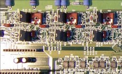
Picked up my second broken Zapco! Must be a glutton for punishment...Anyway... first thing I did was to look at the mess that those 4 caps make when they leak. Well, only one leaked, the far left side. Want to say it's channel one, or left front channel. Pulled all 4 caps then started to clean. When I was brushing around the leak area, one SMD res and semi came off. That's corrosion at work! I replaced the caps and some other 10uf caps, put it back together and tested it. (I think I was the first one to take the amp apart since factory). When it turns on, the idle current is about 1.75amps, good so far. The rear input clip light stays on with no other lights on except the green on light. Then after about 4 second it goes into protect mode and starts the process over. There is negligible dc voltage at the speaker outputs, could be my meter, guess I should have a look at it with a scope, and the front end semis and finals look nice with no shorts.
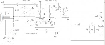
My Question is does anyone know if the input clip circuit is after the op-amps and after the front end, before the finals? The Soundstream amps have it before the front end boards, after the op-amps.
Guess I could half split it and I haven't ruled out that NAND gate. I'll play some more and write what I find.
BTW. this is scott-leanne that did the post on one of these years ago and I cant remember the password or email address I used the last time I posted.
OK... I replaced the 10uf cap next to the NAND gate pins 12 and 13 with a 100uf for now until I can order some new gates. Next I wanted to see any dc voltage on the spk outputs with a scope. I turn the system on and the rear input clip light comes on along with the power on green light, Idle current still good, then it goes into protect and stays there. It does not try to restart, that tells me the NAND gate is flakey. I think I found one possible problem with the scope.
When the system is on for 4 seconds, the dc voltage on ether rear channels is about .3 volts or less. While its going into protect, the left rear spk output goes to about 5vdc. None of the other channels do this. Am I on to something? Guess I need to pull the finals out of circuit and check them or should I dissect the front end and possibly op-amps for this channel?
Any body??? Suggestions???

Picked up my second broken Zapco! Must be a glutton for punishment...Anyway... first thing I did was to look at the mess that those 4 caps make when they leak. Well, only one leaked, the far left side. Want to say it's channel one, or left front channel. Pulled all 4 caps then started to clean. When I was brushing around the leak area, one SMD res and semi came off. That's corrosion at work! I replaced the caps and some other 10uf caps, put it back together and tested it. (I think I was the first one to take the amp apart since factory). When it turns on, the idle current is about 1.75amps, good so far. The rear input clip light stays on with no other lights on except the green on light. Then after about 4 second it goes into protect mode and starts the process over. There is negligible dc voltage at the speaker outputs, could be my meter, guess I should have a look at it with a scope, and the front end semis and finals look nice with no shorts.
My Question is does anyone know if the input clip circuit is after the op-amps and after the front end, before the finals? The Soundstream amps have it before the front end boards, after the op-amps.
Guess I could half split it and I haven't ruled out that NAND gate. I'll play some more and write what I find.
BTW. this is scott-leanne that did the post on one of these years ago and I cant remember the password or email address I used the last time I posted.
OK... I replaced the 10uf cap next to the NAND gate pins 12 and 13 with a 100uf for now until I can order some new gates. Next I wanted to see any dc voltage on the spk outputs with a scope. I turn the system on and the rear input clip light comes on along with the power on green light, Idle current still good, then it goes into protect and stays there. It does not try to restart, that tells me the NAND gate is flakey. I think I found one possible problem with the scope.
When the system is on for 4 seconds, the dc voltage on ether rear channels is about .3 volts or less. While its going into protect, the left rear spk output goes to about 5vdc. None of the other channels do this. Am I on to something? Guess I need to pull the finals out of circuit and check them or should I dissect the front end and possibly op-amps for this channel?
Any body??? Suggestions???
Last edited:
if i have learned anything about old school soundstream is their individuality and weakness/strength is all one in the same. unless someone has verified similarities in this amp, i would look at more similar amps. however, in a soundstream, it monitors the voltage differential between the rail and output. speaking soundstream, if outputs are okay, then the first place to look would be the feb connections (with a meter probe, not just naked eye)
however, this is zapco..... what is the voltage to/from the drivers giving 5v? ".3 or less" is fine by me, but 5v is substantial, and certainly a/the problem. you have the board in fromt of you and 3 good channels to compare...
however, this is zapco..... what is the voltage to/from the drivers giving 5v? ".3 or less" is fine by me, but 5v is substantial, and certainly a/the problem. you have the board in fromt of you and 3 good channels to compare...
When the system is on for 4 seconds, the dc voltage on ether rear channels is about .3 volts or less. While its going into protect, the left rear spk output goes to about 5vdc just for a split second. None of the other channels do this.
Should have added this..
The last one of these I mest with, none of the finals were bad and its not too fun pulling them out. I will post more on what I find. I'm going to start on the op-amp/pre-amp area first.
Should have added this..
The last one of these I mest with, none of the finals were bad and its not too fun pulling them out. I will post more on what I find. I'm going to start on the op-amp/pre-amp area first.
i suppose it kills rail voltage, and thus the pre-amp power when in protect, making it hard to find the dc source. i would venture to say it should be present in the 4 seconds if before the mute circuit, and show up if after. it may be possible to keep mute active to test further.
During some testing I replaced, one at a time, some opamps and after replacing one of them, the amp powers up. I found that if I put audio in the front input and selected 4 channel, I could only get sound from the left rear channel... Front channels work fine. When I switch it to 2 channel input, both channels on the rear work. I kept replacing the opamps until the rear input worked on both rear channels. Also I found that when its in 4 channel mode and I put the crossover to high pass on the rear and select 24dB slope the right rear channel cuts off. I suspect that the opamps on the crossover are flakey also. I also noticed when I was replacing opamps, the dc voltage on the outputs would change. So as it sits, the DC on the front channels is .001 or less. The rear had .44 on the right and .001 on the left unless I swap an opamp the it would change. There is a little static on the rear left at idle. Idle current is about 2.5A. All the op amps I used were from the previous zapco I fixed so some of them are questionable. It does plays very clear but I know I need to change the opamps with new ones.
So next is to order opamps and replace them all as I think someone really gave the inputs to this amp hell. I can't imagine how it had been hooked up, speaker outputs from the factory radio jammed into the the inputs? I just don't know.
Will let yall know the outcome.
So next is to order opamps and replace them all as I think someone really gave the inputs to this amp hell. I can't imagine how it had been hooked up, speaker outputs from the factory radio jammed into the the inputs? I just don't know.
Will let yall know the outcome.
Side note...
When I first got the amp to stay on, the left rear speaker was moving, low rumble with static. Thats what bad opamps seem to do on these Zapcos. And I dont know how accurate my HP power supply current meter is but it show about 3.5 Amps idle, kinda high I think. The owners manual says 2Amp idle so I dont know. I did change a couple more opamps and there is .000 to .001 VDC on any of the speaker terminals so thats good but I didn't change any on the crossover yet. I think the noise is coming from them.
When I first got the amp to stay on, the left rear speaker was moving, low rumble with static. Thats what bad opamps seem to do on these Zapcos. And I dont know how accurate my HP power supply current meter is but it show about 3.5 Amps idle, kinda high I think. The owners manual says 2Amp idle so I dont know. I did change a couple more opamps and there is .000 to .001 VDC on any of the speaker terminals so thats good but I didn't change any on the crossover yet. I think the noise is coming from them.
I noticed on the last Z400 that I worked on, the idle current was little over 2 amps using the current meter on my HP power supply. This one is 3.5 to 4 amps idle. So my question is- I don't know if someone messed with the bias pots on this amp. Is there an effect of bias adjustment on idle current draw? I have not touched them yet...
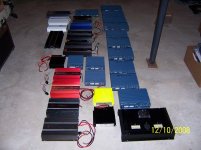
Attachments
yes, there can be a great effect. i have had little 250watt amps peg out 15amps off bias adjustment. too little, and you get bad signal distortion, mostly at lower volume. have you adjusted bias pots before? come to think of it, deviations between components being swapped out can effect the bias, as well.
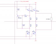
I did not change any of the pre or finals. We talked about it at work and I'll measure the bias on the base first. I think I can turn them down all the way, inject a 1000hz signal to the input, look at the output with my scope and turn them up until the sine-wave smooths out. I know the bias should be about .6 or .7 volts for class A, if I remember correctly. I am going to wait untill I install new op-amps be for I do this.
Someone tell me if I'm wrong
Someone tell me if I'm wrong
Last edited:
I suggest you start at 100 micro-volts as measured across the emitter resistor pairs for each set of outputs as simple voltage drop. 0.001 DC Volts should be adequate and is the most common bias settings for PPI, ZAPCO, PG, RF, etc...most Japanese made amps like Kenwood, Alpine, Pioneer, etc... were using 2 to 4 milli-volts DC voltage measured the same way. These are "Old school" settings from memory but as Rockford Fosgate says in their final test doc's "don't kill the music " right in their bias settings remarks
- Status
- This old topic is closed. If you want to reopen this topic, contact a moderator using the "Report Post" button.
- Home
- General Interest
- Car Audio
- Zapco Z400C4-SL... Not Again!