So, I just received this JL250/1v2 amp (used) and tried to place it into my current aftermarket system to power my sub (JL 8w7) only to find out that no matter whether I have a remote input connected or not to this amp stays on (green light, sounds good). Would be great if I wasn't worried about drain on my battery.
I have ran DMM tests on the amp and here are the results (all of these tests are done with the car engine off but electrical on):
Gnd to 12V: 12.5V
Gnd to Remote (no remote wire connected, 12V connected): 5.4V
Gnd to Remote (no remote wire connected, 12V disconnected): 0.02V
I currently have the car battery going to a 2 farad cap which then is distributed to the 2 amps (a JL 300/4 and the JL250/1v2). All power and ground wires are 4AWG and all 3 devices have separate grounds bolted into the frame. Any other thoughts before I give in to the fact that the 250/1 might be faulty?
Other things to note: I tried putting a remote wire on the amp, no difference however the remote wire is 18AWG and split between multiple devices (both amps and the capacitor). Thinking I need to put a relay in line for remote wire in the future.
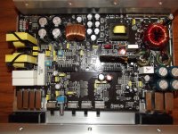
Have you pulled the cover to see if you can see anything obvious?
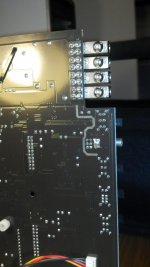
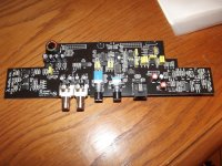
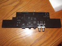
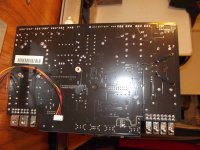
On the preamp board, the 3 op-amps and switching power supply (tiny transformer) are part of the signal sense circuit. The right end of the preamp has the various control circuit components. Remove the board an look at the bottom of it to see if you see any green corrosion. If you do, don't wipe it or remove it yet.
On the preamp board, the 3 op-amps and switching power supply (tiny transformer) are part of the signal sense circuit. The right end of the preamp has the various control circuit components. Remove the board an look at the bottom of it to see if you see any green corrosion. If you do, don't wipe it or remove it yet.
Everything on the board looks in pretty good shape. I believe I've taken a shot of the 3 op amps u were talking about and the backside of the board where they are soldered into.
I'll try to get some shots of the entire front side and back side of the board. By the way Perry, thanks so much for your help.
I'll try to get some shots of the entire front side and back side of the board. By the way Perry, thanks so much for your help.
Attachments
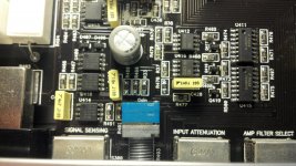
Well I'm not sure if this is a big indicator but I find that when the signal sensing switch is supposed to be on (resistance being 0), i get zero ohms on the switch (good?). However, when the signal sensing switch is supposed to be off, I'm showing 22.6k ohms. The other 6 pin slide switches (input voltage and infrasonic filter) are showing infinity when off and 0 when on.
Could this be my problem?
Could this be my problem?
I think before I start soldering anything on the board (which looks like it may be the only way to fix the signal sensing), I'm going to try and pickup a relay of some sort and just put that in series with the B+ line and use it as the on/off remote switch to the amp and leave signal sensing off on the amp (especially since I don't care to ever use the signal sensing part of the circuit).
Do you read 0 ohms between the terminals of the diode near the remote terminal and two of the end pins of the signal-sense switch?
Could you be a little more specific, maybe pinpoint which diode on the board from the images?
And when you say two of the end pins of the signal-sense switch, any combination of the end pins? there are 6 pins on this slider switch.
- Status
- This old topic is closed. If you want to reopen this topic, contact a moderator using the "Report Post" button.
- Home
- General Interest
- Car Audio
- JL 250/1v2 always turned on