Perry, I’ve got a Orion 4100GX amp and I recently went to test to find the amp caused my power supply to go into current control(~21A). I found that one of the two amps inside(the right channel) was causing the problem. I did some initial measurements to try and see where the issue was and ended up removing the 4 rectifiers (MUR810). These tested fine(forward drop of .42V and no connection in reverse). Further probing of the device without the rectifiers, I saw that one of the power rails showed a 1.2kohm impedance where all others showed greater than 1Mohm.
I did try testing to ensure the issue was only after the rectifiers, however found the amp to draw ~1.5A and quickly turned off the power supply. I did note that the current remained flowing even after removing the turn-on wire.
Do you have any suggestions on what I should test and the best way to do so? From the measurements, it seems like the issue lies on the power supply with the low impedance, however I cannot explain why the amp draws current without rectifiers in place.
Connect only one red power wire at a time to see if the amp will power up both channels (one at a time).
You'll need to reinstall the rectifiers.
These old amps have a lot of defective capacitors. You should plan on replacing every capacitor in the amp. Also expect to have a fair bit of damage to the small traces. A fiberglass scratch pen helps to clean them up to make them accept solder better.
You should also confirm that the vias are intact for any capacitor that has leaked electrolyte.
I took out the large power supply caps and that did not fix the impedance issues I’m seeing.
I think the problem is with the negative rail of the power supply.
On the bad side of the amp, I measure 2.98M ohm from positive to common and 864 ohm from common to negative supply. This is with rectifier and caps removed.
On the good side of the amp, I measure impedances of 307k from positive to ground and 1.1M from negative to ground (with rectifier and caps in place).
I’m pretty sure the 860 ohm across the negative power supply is the issue, but I do not have an idea for what components to check.
I measured the impedance of the capicitors I removed and found they all seemed good(meter went low, then up to about 300kohm). Is this a good test or could they still be bad capacitors? Also, should I be looking at the other electrolytics and/or the film caps as well? I do not see any ones that look damaged or leaking.
Do you have other suggestions on what some other likely problems would be?
Do you have other suggestions on what some other likely problems would be?
Yes. When first starting I found trying to power both channels drew excessive load, however when I disconnected the right channel the left tested fine. When connecting just the right channel, I expereienced the excessive load.
Is there further testing I should do with 1/2 the amp powered?
Is there further testing I should do with 1/2 the amp powered?
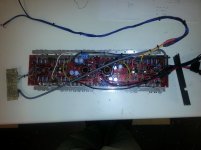
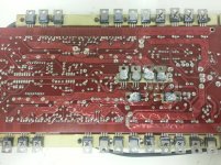
Perry, I used a thermal camera to evaluate and have attached pictures. All pictures are alighed with left side of the amp corresponding to the good channel, right to the bad.
Note testing was done without heatsink, for this reason I did not leave power on for long(pics were taken 5-10 sec after attaching turn-on cable, one channel at a time)
It looks like heat is spreading through most the TO packages. You can see from the image of the left(good) channel that running the amp without a heatsink does not cause all the TO packages to heat up.
The only thing I could think of is that there is a short in the output. I checked the output impedance and both channels are at about 1kohm.
What area of the circuit should I be paying attention to? Could it be a failed transistor in the output stage that is causing all the earlier stages to experience excessive current?
Attachments
That does seem to be the issue. Before removing the component I measured resistance to be ~200 ohms between pins 2 and 3. After removing it went up to Mohms.
I'm looking to find out what the part number is. The numbers are not legible, but it looks like 2N6438. I can only find that part as a TO-3, so it doesn't look like I'm able to read the part number well enough. How can I go about finding the part number, or selecting an appropriate alternate?
I'm looking to find out what the part number is. The numbers are not legible, but it looks like 2N6438. I can only find that part as a TO-3, so it doesn't look like I'm able to read the part number well enough. How can I go about finding the part number, or selecting an appropriate alternate?
Thank you Perry. By the way I did go ahead an turn on the amp(no load) to ensure the short was fixed and both channels now draw standby current of ~.8A.
I'll go ahead and replace all 6. Should I also be replacing the complementary 2N6490s or is it only important to change the ones in parallel with each other?
I'll go ahead and replace all 6. Should I also be replacing the complementary 2N6490s or is it only important to change the ones in parallel with each other?
I tested the amp and after about 15 seconds on I heard a noise and smelled some smoke. I turned it off quickly, but now when I turn it on it draws ~15A (current limited on my power supply).
I am trying to trace the problem and I've found that there is no voltage on one of the inputs to the transformer, so I suppose it's the drive circuitry, but I am unsure how this amp is laid out. What components should I be look at or what tests should I perform?
I am trying to trace the problem and I've found that there is no voltage on one of the inputs to the transformer, so I suppose it's the drive circuitry, but I am unsure how this amp is laid out. What components should I be look at or what tests should I perform?
- Status
- This old topic is closed. If you want to reopen this topic, contact a moderator using the "Report Post" button.
- Home
- General Interest
- Car Audio
- Orion 4100GX - right channel out