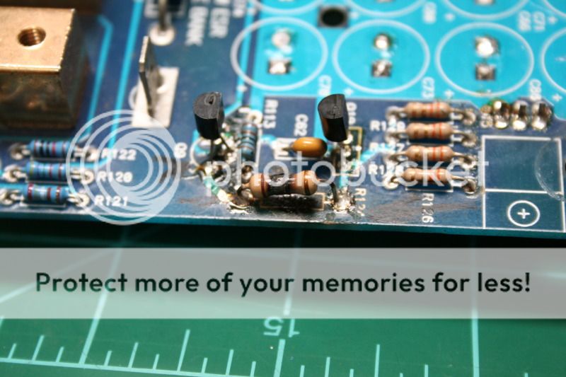
I think this is my first post here, and must say the option that pops up with search results before starting a thread is awesome. While it brought up threads I had already read after searching on my own, I think this is something all forums could use. Now back on topic..... I have a blown Ref 1000sx amp I am repairing and need to find the proper resistance for a burnt up resistor. In the thread by mike49504 there is conflicting info, talking about the R124 spot taking a 3.32ohm, or a 7.5ohm, or even a 15ohm. Just looking for clarification as to which I should use. The R124 on this board is a part of the power supply, and here are some pics for reference.
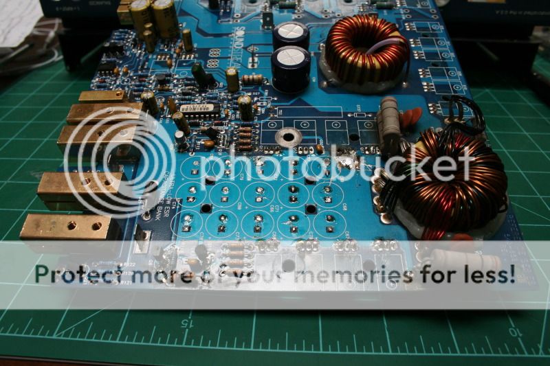
Im back with another resistor question. I finally have the amp all back together and it seems to be working pretty good however the very large resistors (piggybacked pairs) are getting hot. After a several minutes they are reaching 200*F, while the rest of the amp barely climbs over ambient (80*F) with the highest temp found being 86*F by the time the resistors are reaching 190*F+ I dont think this is normal, can anyone verify? The color bands are all faded away, but both pairs are reading 1ohm each when tested at the board connections, and rise in temp almost equally.
1 ohm 5 watt is what I have info of. They used a couple 3 watters to get the 5 watt rating in your amp. Yes they run hot to the touch in many cases to the point of color band fade. I have replaced them with sand blocks in the past without issue.
The caps attached to those resistors form a simple snubber type filter, are they in spec also? Rails on secondary should be +&- 37.8 volts DC respectively....
I see a non-original gate totem pole driver in there for Q10 and Q19. The 2SA1562 is spec'ed but its not there, the other is a simple 2N2222 metal can transistor usually also for Q20 and Q9..
hope some of this is useful...
Yes, the Q10 & Q19's were previously replaced with "A1266" transistors, are these sufficient or is there a better part recommended?
The Q20 is the original part, and the Q9 was previously replaced with "MPSA06" transistor. Unsure if that is also a good substitute.
The voltage at the rail caps are +46.9v & -46.9v, quite a bit higher than 37.8 but could that be because my power supply is putting out 14v & not 12v? Or is the PSU drivers allowing excessive voltage (& the reason for the extra hot resistors?)
Also forgot to add, I cannot get the link you provided to work 1moreamp.
Sorry the link is a smile that did not copy correctly so no info there...

I only use the original drivers so I have not had to use replacements perhaps someone could recommend a few devices. The 2N2222 can is widely available, the 2SA1562 might have replacements but as I say I still have some NOS of them here back when I stocked parts like a mad man.
The rail voltages I quoted are spec'ed in my info. What is it idle current draw from your 12 volt supply side?
Lol, and here I thought I was really missing out on something good.
I found a thread about a Ref400 where Perry recommended a BD140 for the 2SA1562, so Im going to give them a try. (reversed mounting as their pins are backward of course)
The amp draws a hair over 2amps at the main fuse when idle, 2.09A to be specific.
I found a thread about a Ref400 where Perry recommended a BD140 for the 2SA1562, so Im going to give them a try. (reversed mounting as their pins are backward of course)
The amp draws a hair over 2amps at the main fuse when idle, 2.09A to be specific.
Hummm. Wrong fets, they should be a NDP7050 or NDP7060, but National Semi stopped making them several years ago now so no direct/exact replacements are likely available.
This might be causing the elevated idle current draw and the hotter then normal resistors that you reported. The IRFZ-48 is a good part but the gate resistors used for the original parts might not be correct with this replacement. I see the original gate resistors have been replaced and the value looks to be correct for the NDP National Semi fets. This along with the gate drivers not being the original adds up to a number device mismatch possibilities.
I would use IRF3205's instead of Z48's for durability and availability reasons and I think the gate resistor value would be more correct for the IRF3205 devices also. You would only need to replace one fet on each side after removing all the Z-48's to test this idea. And if it dropped the idle current draw and the resistors ran cooler, then filling the other positions would be the next best step.
33 to 47 ohm is typical for a Z-48 fet and just about anything below 22 ohms would likely work for the 3205 device . The 3.3 ohms original gate resistors are about the lowest gate resistor values you will likely ever see in use in any car amp. You could try raising the gate resistor values on the Z-48's if you like also . I would jump to 47 ohms based on what other amps use running the Z-48 devices.
As for the drivers and Perry's suggested replacements You can pretty much bank on anything Perry recommends you to do IMHO, so I say go for his suggestions also. if none of the original parts can be had for this amp....
Makes sense, too many tiny variances from original spec and things start to get thrown off further down the line. I searched around & couldnt find what the original FETs were, or a suggested substitute so I opted to just stick with what had been used, go figure it was wrong.
So what you are saying is I could try replacing the 3.3ohm gate resistors (8 total, 1 per FET) with 47ohm resistors, and see if that brings the rail voltages back down? (& that is 47 not 4.7 right?)
If so I can try that right now, I have lots of resistors and if it doesnt work I can always order the IRF3205's & swap back to the 3.3ohm resistors.
Yes you can try to augment the gate drive resistors to operate the Z-48's better and yes the typical gate resistors for the Z-48 are usually in the range of 33 to 47 ohms on all the amps I ever worked on in my past. It is the cheaper alternative right now. I would do the driver circuitry replacements that Perry suggested first though...
The original fets were nation Semi NDP7050's and you could use NDP7060's , but they don't make them any longer. I would use RFP70N06 devices if they are available to you from your suppliers. The IRF3205 is a very robust part but here again you would have to play with the gate driver resistor probably as I am not sure about the 3.3 ohm original part being the best choice. It would help to have a scope to look at these signals to help determine if I am right or wrong with my advice.
I have rails of old stock parts here I bought long ago so I rarely alter from stock parts on any amp.
I was a poor repair tech back then as I bought up all available surplus supplies of fets and transistors as they became available long ago. Now I have an apple box full of unused NOS parts in anti-static protective rails sitting under my bench lol...
Its always good to stock up on stuff, because you just never know.
Ive got the right driver circuitry already on order, but would it be unwise to swap in the 47ohm resistors & give it a go with the parts it has now? I plan to get the right parts put back in, but curious now and we all know what happens then (with curiosity)........
Ive got the right driver circuitry already on order, but would it be unwise to swap in the 47ohm resistors & give it a go with the parts it has now? I plan to get the right parts put back in, but curious now and we all know what happens then (with curiosity)........
You can try it. My apprehension is if you fail a gate driver all the fets will be driven into full enhancement and unless your using a current limited supply then all those Z-48's might end up in the trash bin.
But its up to you really. I use several power supplies on my bench but all of then offer both voltage and current control, so I can control what happens when I fire things up the first time. In the case of your SS amp I would limit out the supply at 5 to 7 amps as this is all the amp needs to fire up properly. And its idle should be around 1.5 amps typically, so a 5 to 7 amp limit will do the job.
If your amp was a old school pre-mosfet design BJT power supply from the late 80's then it would need more power to turn on without spiking your supply down and causing on off hiccups. Older BJT power supply amps need a good 10 to 15 amps to turn on without tripping the amps circuitry to cycle the amp on and off without a successful start up latch on of the amps power supplies.
.. hope some of this helps..
Time for an update. I replaced all of the PS fets with RFP70N06's, I replaced all of the gate resistors with new 3.3ohm resistors, I replaced the 2N2222's & I replaced the 2 2SA1562's (which had already been substituted with something else) with BD140's. Nothing has changed, the rail voltages are the same high reading as before, the large resistors are still heating up quickly, and the idle current draw is still also the same. Frustrated & defeated, but Im still too stubborn to give up. What should I look into next? Im not the best versed in PS systems, but it seems whatever sets the target rail voltage is out of spec but I know not what component is responsible for that. I thought that was what the 2N2222's were for, but maybe I should increase the resistance of the gate resistors beyond 3.3ohms?
In all honesty I cant really say it is, but from the feedback and info Ive gotten from this thread & several other Reference amp repair threads that it seemed a logical reason.
I cant imagine they are supposed to be exceeding 200*F under regular operation, and I have not found any threads mentioning a similar issue. I have some 10w resistors I can swap in to replace the piggybacked 3w ones, which should better handle the heat, but I have no idea what temp they will continue to climb to because I kill the power after it breaks 200*F. (temps taken with IR thermometer)
I cant imagine they are supposed to be exceeding 200*F under regular operation, and I have not found any threads mentioning a similar issue. I have some 10w resistors I can swap in to replace the piggybacked 3w ones, which should better handle the heat, but I have no idea what temp they will continue to climb to because I kill the power after it breaks 200*F. (temps taken with IR thermometer)
- Status
- This old topic is closed. If you want to reopen this topic, contact a moderator using the "Report Post" button.
- Home
- General Interest
- Car Audio
- Soundstream Reference 1000SX repair