Well to start with your gonna need to remove all the blown fets on the burnt side and start cleaning everything up with some solvent< I like to use acetone, and for speed and time sake you can just clip the leads on all the burnt fets for now to get them out of the way, and to ease removal one lead at a time. >.
Once everything is cleaned up and all the soot is removed you can see clearly what else is burnt like gate resistors, and gate drivers etc..It is very unusual that only one side of the fets burnt the way they did. Please clean and inspect the mica insulator underneath those burnt fets and see if it has any burrs of metal shorting thru the mica. Seen that a bunch if times also.
With only one side of the supply burnt I am also worried your power transformer or common mode noise filter may be shorted.
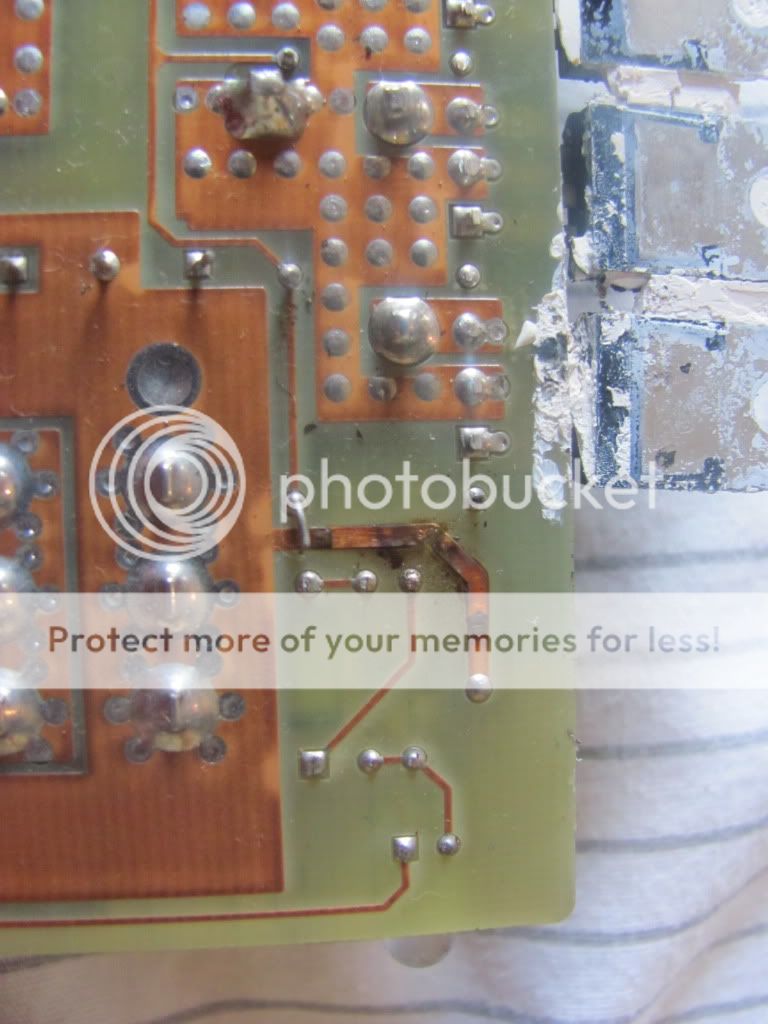
The burnt ground connection is also unusual also as it also points to a short to the case ground somewhere on the amp. We will need to find that issue and correct it along with burnt devices.
Also have you read Perry Babin's tutorial if so then your ready to meter the outputs and diodes to see if any of them have failed also. If not then please click the links below any of his thread posts to get to his training site. His site will guide you on all the most important things you will need to know. I borrowed them and added them below...
Links >> Basic Car Audio Amp Repair --- Basic Car Audio Electronics --- Basic Transistor Testing --- Basic Switching Power Supply Design --- Basic Computer Skills << Links
Once everything is cleaned up and all the soot is removed you can see clearly what else is burnt like gate resistors, and gate drivers etc..It is very unusual that only one side of the fets burnt the way they did. Please clean and inspect the mica insulator underneath those burnt fets and see if it has any burrs of metal shorting thru the mica. Seen that a bunch if times also.
With only one side of the supply burnt I am also worried your power transformer or common mode noise filter may be shorted.
The burnt ground connection is also unusual also as it also points to a short to the case ground somewhere on the amp. We will need to find that issue and correct it along with burnt devices.
Also have you read Perry Babin's tutorial if so then your ready to meter the outputs and diodes to see if any of them have failed also. If not then please click the links below any of his thread posts to get to his training site. His site will guide you on all the most important things you will need to know. I borrowed them and added them below...
Links >> Basic Car Audio Amp Repair --- Basic Car Audio Electronics --- Basic Transistor Testing --- Basic Switching Power Supply Design --- Basic Computer Skills << Links
Well to start with please repair the burnt ground trace on the bottom of the board. This is a symptom of a problem so its probably OK to repair it first and get it out of the way. A simple jumper made of solder wick will do, but do not use too big of a conductor as this trace was meant to open like a fuse and not burn the board up.
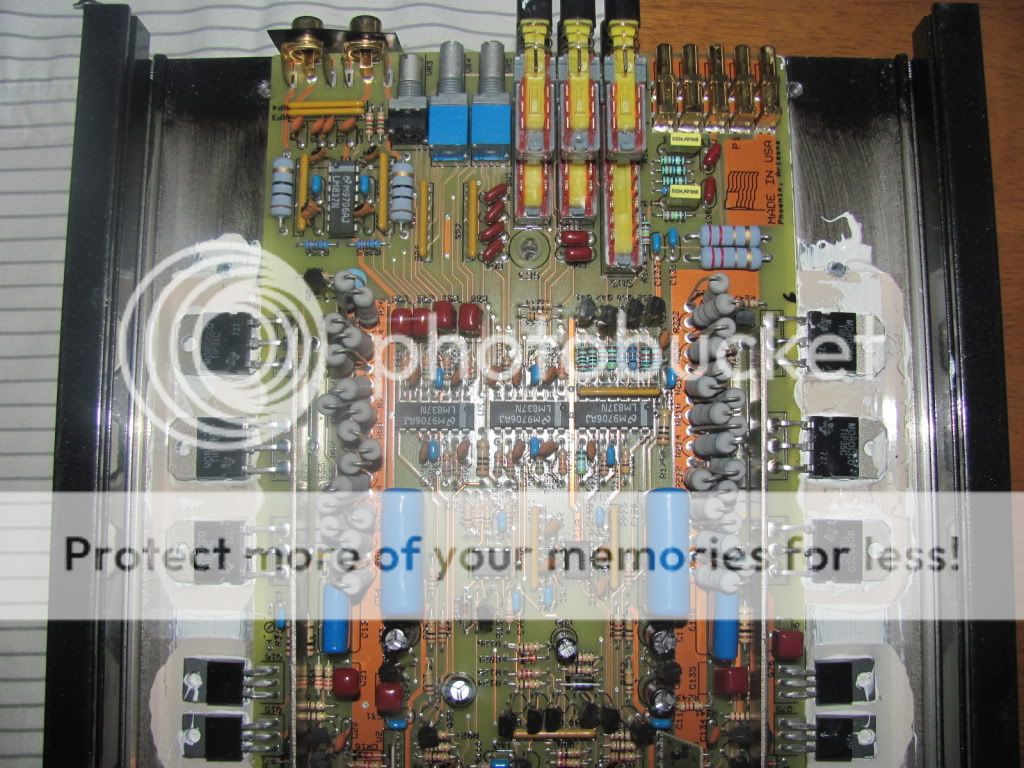
With a amp like yours where the fets have failed, I usually start looking for why they failed the way they did. I suggest that you inspect the mica insulator underneath those burnt fets to see if there are any holes or debris compressed thru the insulators causing the short that has occurred. I have seen mica do this over the years and although its a natural material found as a stone based product it can be cut and damaged so it can allow a short to occur to the sink. I have seen this on Audison, PPI, and others that use this product. Usually it was metal fragments from the screw holes that hold on the bottom of the case.
Also I use a 1 inch paint brush dipped in acetone and a stiff animal hair bristle brush to clean up some more of that soot that is still on the board and components. It is conductive and can cause issues so its best to keep cleaning as best as possible.
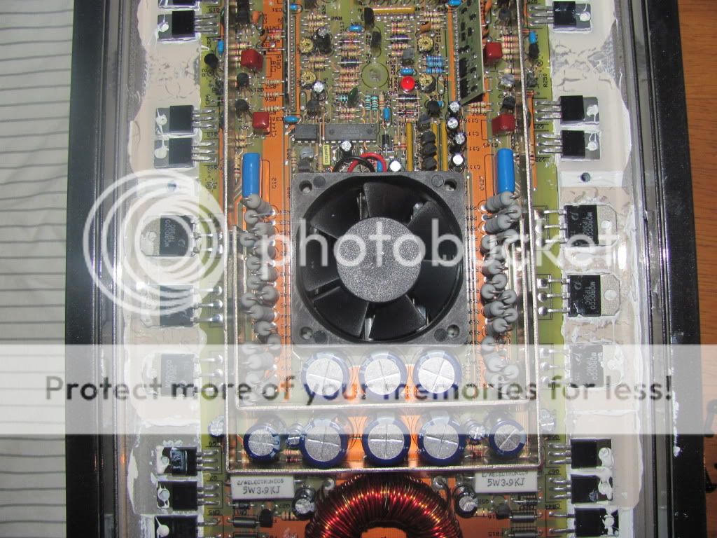
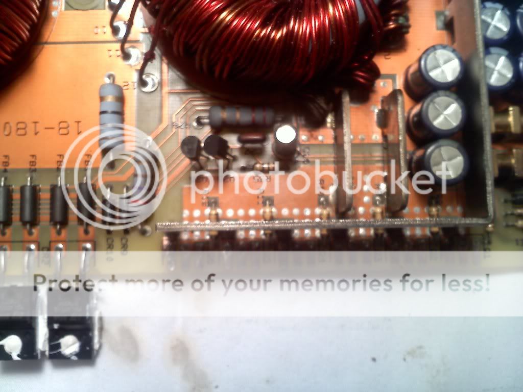
Also if you have a DMM or DVM please ohm out all the gate resistors and the current limits on the gate driver transistors, I am fairly sure the gate driver transistors did not survive this failure. The gate drivers are those two little to-92 transistors near the power toroid. They often fail and are cheap to replace. MPSA-56 and MPSA-06 are their device numbers.
Let me know what you find on the resistors and drivers and what not....
With a amp like yours where the fets have failed, I usually start looking for why they failed the way they did. I suggest that you inspect the mica insulator underneath those burnt fets to see if there are any holes or debris compressed thru the insulators causing the short that has occurred. I have seen mica do this over the years and although its a natural material found as a stone based product it can be cut and damaged so it can allow a short to occur to the sink. I have seen this on Audison, PPI, and others that use this product. Usually it was metal fragments from the screw holes that hold on the bottom of the case.
Also I use a 1 inch paint brush dipped in acetone and a stiff animal hair bristle brush to clean up some more of that soot that is still on the board and components. It is conductive and can cause issues so its best to keep cleaning as best as possible.
Also if you have a DMM or DVM please ohm out all the gate resistors and the current limits on the gate driver transistors, I am fairly sure the gate driver transistors did not survive this failure. The gate drivers are those two little to-92 transistors near the power toroid. They often fail and are cheap to replace. MPSA-56 and MPSA-06 are their device numbers.
Let me know what you find on the resistors and drivers and what not....
All the gate resistors should read the same...Could you ohm-meter the fets on the other side across any two leads and see if any are shorted?
The gate drivers are so cheap and plentiful I just replace them as a matter of common practice. They cost me 3 cents each to buy in bulk. So just for good practice replace them, they rarely survive a failure like this, better safe then sorry, plus a ohm meter will not tell you if they are leaky anyway, and I don't know weather your in reach of a scope to check the drives with. So be safe, and just replace them regardless.
All the gate resistors you measured should read the same in circuit The 10 & 17 ohm readings are questionable. that is why I want you to meter the undamaged fets. They possibly have failed also. If so then I would replace a couple of the fets < one on each side >and verify all the gate resistors and then replace the drivers. This should bring your power supply back to life. two fets one on each side is enough to power up your amp with for simple testing as to basic idle and such.
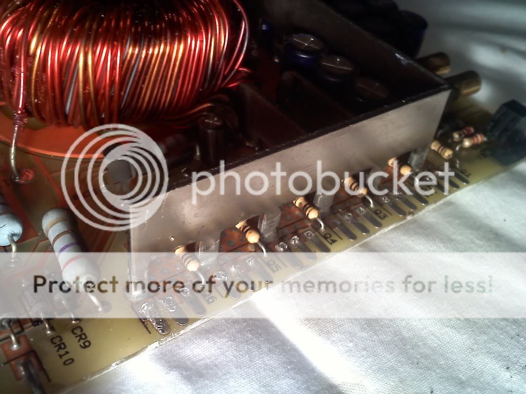
While your at it please meter your outputs and drivers in the audio sections. I don't want to overlook the possibility that a failure in that area has caused all of this. the outputs are the TIP-35 and TIp-36 devices, and there drivers are the smaller transistors in between the TIP's.
We are still looking for a reason why this happened, so the two fets back in the supply is enough to power up the amp for basic idle nothing more. but to do that we need to check all the other things first and clamp the amp board back into its sink for initial power up testing.
Let me know what you find....")
The gate drivers are so cheap and plentiful I just replace them as a matter of common practice. They cost me 3 cents each to buy in bulk. So just for good practice replace them, they rarely survive a failure like this, better safe then sorry, plus a ohm meter will not tell you if they are leaky anyway, and I don't know weather your in reach of a scope to check the drives with. So be safe, and just replace them regardless.
All the gate resistors you measured should read the same in circuit The 10 & 17 ohm readings are questionable. that is why I want you to meter the undamaged fets. They possibly have failed also. If so then I would replace a couple of the fets < one on each side >and verify all the gate resistors and then replace the drivers. This should bring your power supply back to life. two fets one on each side is enough to power up your amp with for simple testing as to basic idle and such.
While your at it please meter your outputs and drivers in the audio sections. I don't want to overlook the possibility that a failure in that area has caused all of this. the outputs are the TIP-35 and TIp-36 devices, and there drivers are the smaller transistors in between the TIP's.
We are still looking for a reason why this happened, so the two fets back in the supply is enough to power up the amp for basic idle nothing more. but to do that we need to check all the other things first and clamp the amp board back into its sink for initial power up testing.
Let me know what you find....
If any do not read 47 then they either elevated in value, or brunt open. Either way they need to be replaced. I would replace them all so they are all new but that is a option to most people. I just like to know they are fresh and in tolerance spec.
On the outputs just measure any two leads as a pair on each transistor. I like to read 1 to 2, 2 to 3.
If any are shorted they will read as such, You can compare A channel to B channel, TIP-35 channel A to TIP-35 channel B. It is doubtful both channels are damaged, so the bad channel will show up as 10 ohms or less across the leads, when the matching device across the board will read like diode junctions.
If any of this is getting too out of hand for you please go to Perry Babin's links for his training site. He has it all explained there with pictures also.
Perry's link below, please see "basic transistor testing"
Links >> Basic Car Audio Amp Repair --- Basic Car Audio Electronics --- Basic Transistor Testing --- Basic Switching Power Supply Design --- Basic Computer Skills << Links
Links >> Basic Car Audio Amp Repair --- Basic Car Audio Electronics --- Basic Transistor Testing --- Basic Switching Power Supply Design --- Basic Computer Skills << Links
I'm trying to keep up but i'm obviously no pro. All of the tip 35, 36's read out 17 ohms. I have read over perry's site time and time again but i keep confusing myself. will the transistors act the same as if they were out of the board? I printed out his test form and have been using that when I go through them(on the board). Just any help is good help and I greatly appreciate your help!!!
Last edited:
all of the TIP35c's look like this
and the TIP36's like this
An externally hosted image should be here but it was not working when we last tested it.
and the TIP36's like this
An externally hosted image should be here but it was not working when we last tested it.
Thank You ! Perry for chiming in. Your help and guidance is always appreciated my friend.
Spicy Mchaggis:
If this is your first time inside a car amp then most of what I have been directing you to do is has been missed or has just flown by misunderstood. For this I must apologize to you. Perry has a wonderful site and it has everything clearly defined and well described to even a laymen at this type of work. He is also a much better teacher then I, as I tend to some what forget that lots of folks are not as experienced as myself. My apologizes to you if any of this has happened to our work here in this thread.
I admire your tenacity to learn and your attempt to preform your own repairs.
I want your gear to get repaired properly, just like Perry does. Your repair can not be completed unless you are able to follow his or my lead while using the info garnered from Perry's web-site on the simple how-to's of which his web-site teaches so clearly.
We still have not located the reason why the power supply failed like it did, and this worries me a bit because if we don't find the reason for all the symptoms your repairing, this amp will go up in smoke the first time you power it up. We are going to have a bit of a tough time trying to get you thru the next few phases if Perry's web-site is not clearly understood on your part. You will need to know how to measure simple transistor ohm meter readings in circuit to get thru the rest of the repair work. So please tell us what it is that Perry's site does not explain fully for you, so we might add in some more details for you in efforts of helping it all to be clear to you.
A suggestion: When measuring transistors and fets in circuit if your reading don't prove clearly what you want to know, then may I suggest that you lift the center leg of any transistor of fet out of the circuit board solder joint and then read across the leads in pairs again with the lifted lead always in the readings, and with the black and red probes reversed for a second set of readings across each device in question. The lifted lead takes part of the device out of circuit so you can get clearer readings from that lead to the other two leads somewhat independent of the surrounding circuitry.
I was just unsure if the transistor readings could be done on the board and what readings I should actually be getting? I have no problem desoldering, so just pulling them to check is no big deal. I'm sorry that I don't know as much as I should for doing this type of repair, but I have always been a do it yourselfer.
ok, so if I get readings like this for a TIP36c then it is good
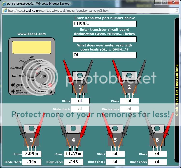
and reverse for TIP35c where 1 and 2 have .5x
what is a good next step if these are all good and the irfz44's and the gate resistors are getting replaced anyways? along with the gate drivers. How can I find a good possible reason all of this could have happened?
and reverse for TIP35c where 1 and 2 have .5x
what is a good next step if these are all good and the irfz44's and the gate resistors are getting replaced anyways? along with the gate drivers. How can I find a good possible reason all of this could have happened?
I was just unsure if the transistor readings could be done on the board and what readings I should actually be getting? I have no problem desoldering, so just pulling them to check is no big deal. I'm sorry that I don't know as much as I should for doing this type of repair, but I have always been a do it yourselfer.
This is all fine and good, but in order to test the possible reasons for the failure the test methods that Perry's web-site teach are pretty much mandatory if success is your desired goal. I am at fault for placing your experience higher then it really was based on your use of terminology in your thread posts.
You do not have to remove the transistors completely to find out if they are shorted. The simple lifting of the center legs of each device will allow you to get definitive readings on most ordinary DMM's. With time and experience you won't even have to do that.
On any amp with multiple outputs like this one, a single bad output device will blur readings across the entire set. They will all look like they are defective when compared to the other channel just across the board. This is due the fact they are paralleled to gain current sharing and power handling factors.
There maybe nothing wrong with the outputs if so channel A will read like channel B. I have seen these amps blow there power supply because the amp was running too low of a speaker load. These are not 1 ohm amps but I have seen this failure because of just that reason. And once the power supply was repaired the amp went right back into service, until it failed again the exact same way due to being run into incorrect speaker impedance's.
Please post your questions about any readings you don't understand like you did for the gate resistors. they were burnt open or up in value and needed to be replaced just like the Mosfets. The gate drivers are likely damaged also so please replace them as a matter principal as they usual do not take this type of failure too well IHMO.
Once you have tested the other possible failure points like the outputs and drivers, then you will need to test the rectifier diodes between the mosfets and the TIP outputs. These are simple diode junctions so reading them is less complicated then transistors.
If all this checks out then we might be a point of reassembly and clamped back into its sink for a simple power on test. but this test should be preformed with some sort of current limit on the 12 volt supply feeding the amp, so you get a chance to see if you missed anything before the amp damages itself again just from testing. A 12 volt head light inline in circuit on the 12 volts supply will work as a current limit.
But all of this is further down the road while your checking all the other possibilities before we get to simple power on testing.
This can be complicated I know. Just because Perry and I can do in our sleep is only because we have done it so many times before its just second nature now to us veterans. Once you have seen it all, it's all the same pretty much. I enjoy it when its something new and unusual, then I learn something new also...
ok, so if I get readings like this for a TIP36c then it is good
and reverse for TIP35c where 1 and 2 have .5x
what is a good next step if these are all good and the irfz44's and the gate resistors are getting replaced anyways? along with the gate drivers. How can I find a good possible reason all of this could have happened?
Looks like they might just be fine. Transistors short junctions when they fail or blow completely open. So be looking for very low ohms across all the leads if they are shorted in anyway. Shorted devices are the most common.
Alright, all of the transistors checked out, everything is cleaned and reassembled. I just want to know the best simple start up procedure for this amp. I understand to put a small fuse in line, is a 15 to big? and you also metioned about putting in a headlight for a current limt. will any headlight work or does it have to be under a certain wattage?
- Status
- This old topic is closed. If you want to reopen this topic, contact a moderator using the "Report Post" button.
- Home
- General Interest
- Car Audio
- PPI PC1400 Help please