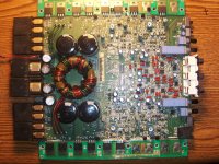
The board number is PC-3094-E
It is alot different from the 600a4. You have the same schematic I do. I believe its the same as the 551X 4 channel the silver with blue emblem. This is the older 2002 model grey heat sink with the red light in the badge.
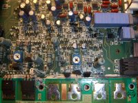
I posted a pic of the board and the section giving me issues.
I dont believe I have the right schematic kinda the same set up as a 400a4 just a little different.
It is alot different from the 600a4. You have the same schematic I do. I believe its the same as the 551X 4 channel the silver with blue emblem. This is the older 2002 model grey heat sink with the red light in the badge.
I posted a pic of the board and the section giving me issues.
I dont believe I have the right schematic kinda the same set up as a 400a4 just a little different.
Attachments
Are the circuits for the output stage identical in the schematic we're using and your amp?
Did you measure the gate-source voltage for Q310/311 when they were in the circuit?
I did not measure the gate to source voltage before removing Q310/Q311 should I pu them in and check?
I am not 100% if the circuits are the same I have a few 600a4's laying around maybe I will pop one open and look. Seems it would be easier to tell that way.
The 550x schematic I have is labeled h400a4.
https://sites.google.com/site/brandescm/home/projects/550Xsch.pdf?attredirects=0&d=1
Not sure its much help.
https://sites.google.com/site/brandescm/home/projects/550Xsch.pdf?attredirects=0&d=1
Not sure its much help.
Back to this amp.
They measure about the same as the rest of the FETS.
Q311 IRF9540 G-S: +2.967 vdc
Q310 IRF540 G-S: -2.438 vdc
Still have the -2.702 vdc on the bridging terminal.........but.......
IF I increase the bias for that channel just until the amp starts to draw current and leave it all the voltage on the bridging terminal goes away but the 2 fets in that channel start to get warm.
Wierd thing is if I am touching the bridging terminal with my meters probe and adjusting the bias at the same time, when I insert the small screw driver into the pot to adjust, touching the screw driver to the metal in the pot makes it draw current, like 8 amps. If I remove the probe from the bridging terminal it does not draw any current when using the screw driver.
It's not straight DC. The channel is oscillating. It appears as DC because the oscillation waveform isn't symmetrical (well, that's a guess).
Clamp the outputs and set the bias so that it goes back to a straight line (minimum bias that achieves that). What is the DC voltage across each of the 0.1 ohm source resistors?
Clamp the outputs and set the bias so that it goes back to a straight line (minimum bias that achieves that). What is the DC voltage across each of the 0.1 ohm source resistors?
I think you are correct, I will do that now. I replaced all the outputs and drivers on that side of the amp.
Its acting like an un biased Power 650. If you view the output throught the scope at an idle, you have to increase the bias to get a straight line and get rid of the noise.
The lower the bias the bigger the haze or noise.
I will check what you asked right now.
Its acting like an un biased Power 650. If you view the output throught the scope at an idle, you have to increase the bias to get a straight line and get rid of the noise.
The lower the bias the bigger the haze or noise.
I will check what you asked right now.
Please read post #52 first.
I set the bias on the 2 channels just until the line went straight. Its drawing about 2 amps current.
R449 0.007 vdc
R436 0.007 vdc
R349 0.033 vdc
R336 0.033 vdc
These voltages were measured across the source resistors.
All channels produce clean audio, but 2 only do as long as the bias is set. I have not tested on speakers yet, but as far as a waveform on the scope 2 have bad ascillation if the bias is not set.
I don't know which channel you set the bias on first so try this. Set the bias fully CCW on those channels and bias the 300 series channel first, then the 400 series channel.
Note the voltage across the 0.1 ohm resistors.
Now go back to fully CCW and bias the 400 then the 300 series channel and note the resistor voltage.
I'm trying to determine if one channel is causing the other channel to oscillate. If only one channel is actually defective, maybe stopping it from oscillating will allow the other channel to be set at a normal bias.
- Status
- This old topic is closed. If you want to reopen this topic, contact a moderator using the "Report Post" button.
- Home
- General Interest
- Car Audio
- Rockford Power 550X 4 Channel