Ok, here is the story..
I have been running this amp for a couple months now with no issues. yesterday I noticed that my tweeters were sounding funny, so i checked them and they read lower than 1 ohm, 3 of the 4 on each front channel were blown. I replaced them, as well as relocated the amp in my truck. turned on the radio, and it shortly cut out. 1 of the new tweeters sounded like crap, so i checked it at the amp, it read .2 ohms, there was a short, I fixed that, and turned the radio on again, same thing, it cut out. so this time i checked all of the speakers, and found another shorted speaker wire, this time on a rear channel. So I fixed that short, checked everything again to make sure everything was ok, turned it on once again. It played for a few seconds, then cut out again.
Now the amp stays in protect mode. It trys to power up, I hear it click, and notice a power draw when it does, but it does not power up, just stays in protect and keeps clicking, and got pretty hot to the touch.
I pulled the cover off of the amp to check for any obvious signs of a prooblem, and have found none. nothing appears burned, or smells funny.
Im confident I can fix this amp myself with a little guidance, which is why I am here.
Im thinking output transistors would be a good place to start, as that seems to be what was getting hot, plus a bit of research last night about amp repair, lead me to believe they are usually a pretty common problem.
Could somebody point me in the right direction ? Thanks in advance.
Hi
Check your voltage supply connection. Most automotive stereo products have a diode to protect against reverse polarity. Typically they are designed to hold up under most circumstances, To test this you need a multimeter, with the power disconnected at the battery check ohms of resistance between V+ and Gnd reading should be high, if its low or worse very low, there is a short indicating condition for high current flow, and further damage to occur.
The complex problems of the speakers may also be explained by a reversal of polarity if Gnd is wired common with battery ground.. ie there may have been 12v+ across them.
Try to strictly follow color coding, and keep any exposed wires away from possible shorts.
In the bigger world you have discovered conductivity vs insulation, its a matter of getting your wiring right the first time.")
Cheers / Chris
Check your voltage supply connection. Most automotive stereo products have a diode to protect against reverse polarity. Typically they are designed to hold up under most circumstances, To test this you need a multimeter, with the power disconnected at the battery check ohms of resistance between V+ and Gnd reading should be high, if its low or worse very low, there is a short indicating condition for high current flow, and further damage to occur.
The complex problems of the speakers may also be explained by a reversal of polarity if Gnd is wired common with battery ground.. ie there may have been 12v+ across them.
Try to strictly follow color coding, and keep any exposed wires away from possible shorts.
In the bigger world you have discovered conductivity vs insulation, its a matter of getting your wiring right the first time.
Cheers / Chris
It likely has shorted output transistors. If you disconnect all speaker wires and the RCA cables from the amp, does it still go into protect?
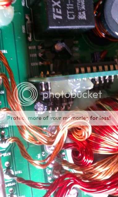
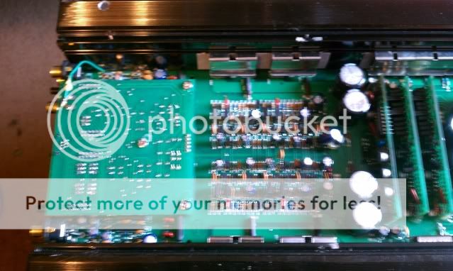
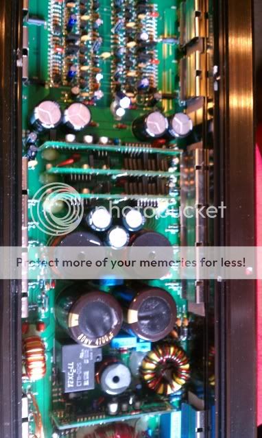
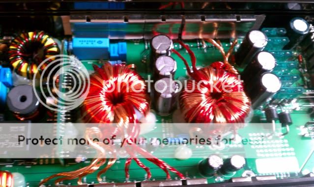
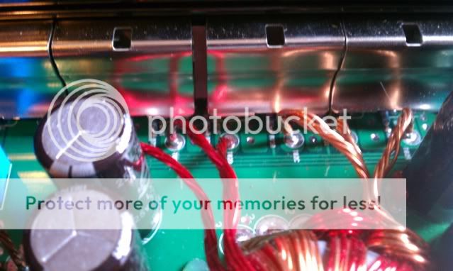
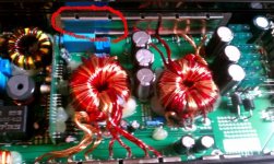
If so, post a photo of the board in the amp.
Yes, I have disconnected everything. speaker wires, and RCA's, and the amp still does the same thing.
I will take pictures and post them in a minute.
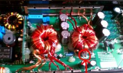
Ok, here are some pics, if you would like something particular, I will get it.


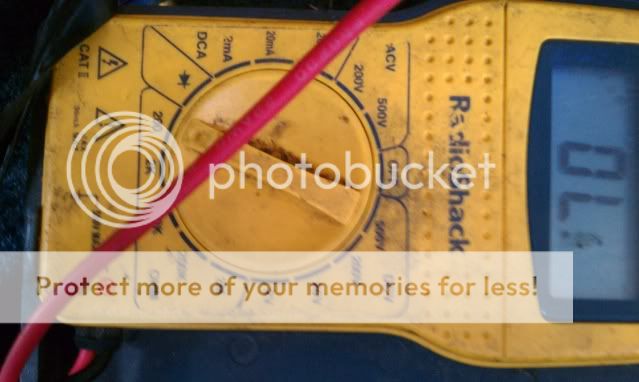
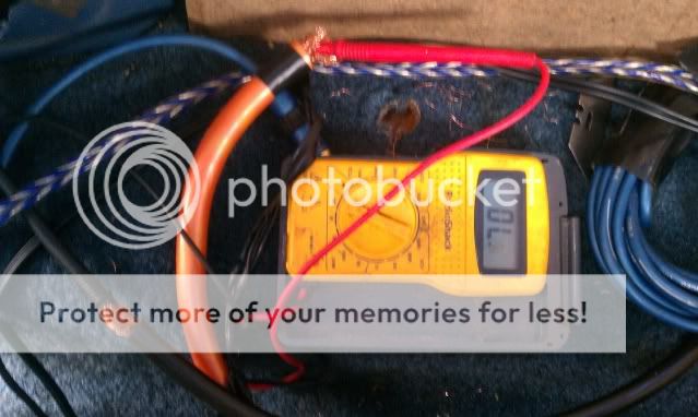
Also, I checked the pos and ground at the amp like stated above with the batteries completely disconnected.
I checked it on all of the ohms settings shown on my multimeter, and get the same reading "OL" . Im no wizz with multimeters, but my experience with this one is that if it reads "OL", then the ohms are TOO LOW for it to read them.
what would be the next step here? backtrack all of my power wires and look for some sort of short?
Remove from the amp all speaker wires and rca connectors as Perry suggested.
Does the amp power up properly?
If so, let the amp on, and measure all speaker outputs with your mm set to DC.
What is the readind ?
nope, amp still does the same thing.
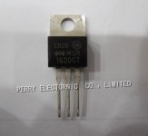
I have the amp out, and am currently checking the output transistors, so far it seems that most all of them are bad.
At this point, I think I should start looking at ordering parts. ?
Yes,but its better to gather all parts you need, in one order.
Can you lift the center leg of the rectifiers?
Nornally, there should be 4 twin rectifiers mounted between power supply fets and output transistors.
I do not follow ...
rectifiers only have 2 legs correct ?
Im sorry if im being complicated, I have never attempted an electrical anything repair before. Im confident I can fix it, Im reading as i work through this, googleing everything I can, but this is alot to take in
I found them, wasnt fast enough i suppose.
Should I remove all of the transistors and rectifiers for testing ? Im kind of reading and working as I go, now im reading everything should be tested outside the amp.
by lift the center leg, you mean just disconnect it, or are you asking if it is loose ? (its not)
Should I remove all of the transistors and rectifiers for testing ? Im kind of reading and working as I go, now im reading everything should be tested outside the amp.
by lift the center leg, you mean just disconnect it, or are you asking if it is loose ? (its not)
the best thing to do is to remove the rectifiers, bent the center leg up in the air and solder them back with their center leg lifted.
I say "the best", because there are only 4 rectifiers to remove, instead of all output transistors...
And then test the amp ?
so much for that. If it wasnt fried before, it is now
smoke from the power module isnt good huh, why did i even open this thing up.
Im more pissed now then i was when the thing quit working
how am i supposed to test anything when i cannot even power it up ? broke 2 of the center legs trying to de-solder the rectifiers.
I should just send it in.
smoke from the power module isnt good huh, why did i even open this thing up.
Im more pissed now then i was when the thing quit working
how am i supposed to test anything when i cannot even power it up ? broke 2 of the center legs trying to de-solder the rectifiers.
I should just send it in.
OL is very high resistance, indicating a open connection,.. with power not applied indicating much better than low resistance. its important to say what you checked... ie one probe was to gnd the other was to the power inlet.
You are entering territory where a schematic diagram would be helpful,
when the amp is externally powered, do you hear the black rectangular relay switch ?
Think of the amp in terms of stages.
Power supply what you have here I see is a inverter stepping 12v+ up to AC voltage to generate a positive and negative rail, probably 30v. So you need to know what rectifiers are doing, So how are the rectifiers arranged ? ...( for efficiency which is what this amps power supply is about converting 12v+ to higher values ) Answer: as a bridge rectifier. A bridge rectifier has 2 AC connections and 2 DC connections. The conversion of AC to DC is that the AC value will be lower, and the DC slightly higher, note your multimeter has a switch for AC and DC.
With the amp externally powered, is everything appearing to be OK ? ie no burning smells etc, so checking the amp.
To measure one probe is likely to need to be touching ground, the other carefully probe the diodes, now diodes terms are anode ( meaning way in - and in roman times was over doors indicating entrance, and cathode way out ) In the case of a bridge rectifier the cathode indicated by the silver band on one side will be AC and the other will be DC- this is the layout of bridge rectifiers, so with your multimeter switched to DC do you see voltage at the cathode - it could be either diode. ? The anodes ( without the silver bar ) on the other hand will indicate negative voltage, or AC so measuring DC again you should be able to measure a negative voltage.
if you have No voltage your power supply stage is down, indicating a failure of component or maybe its protection circuitry has kicked in. Protection may include the diode I referred to in my first reply. These are arranged with anode from ground and cathode ( silver bar ) to the positive supply. Protection may also be a current limiter, and this could be the purposeof the black relay, Most relays are transistor activated at a low current, so look up about protecting circuits with relays. Relays have coils to activate the contact(s). If the relay is protecting there is a reason why no voltage or voltage ( relays have two states ) is getting to the coil.
Cheers / Chris
so much for that. If it wasnt fried before, it is now
smoke from the power module isnt good huh, why did i even open this thing up.
Im more pissed now then i was when the thing quit working
how am i supposed to test anything when i cannot even power it up ? broke 2 of the center legs trying to de-solder the rectifiers.
I should just send it in.
oh dear, at this point yes you are annoyed, its a powerful lesson that electronics has many rules, Yes the repair shop, or replacement is needed. You may find replacement is less costly. If selling this one on eBay be truthful to your buyer that it needs repair. But once you have cooled down work out what happened... one of my worst embarrassing moments was putting a differential in so that the car had 4 reverse gears, and one forward.. I spent the rest of the day with differentials up to my eyeballs and just laughed. ... er later, thankfully it was my car too,
Sorry things did not work out.
Cheers / Chris
Last edited:
oh dear, at this point yes you are annoyed, its a powerful lesson that electronics has many rules, Yes the repair shop, or replacement is needed. You may find replacement is less costly. If selling this one on eBay be truthful to your buyer that it needs repair. But once you have cooled down work out what happened... one of my worst embarrassing moments was putting a differential in so that the car had 4 reverse gears, and one forward.. I spent the rest of the day with differentials up to my eyeballs and just laughed. ... er later.
Sorry things did not work out.
Cheers / Chris
Oh, im not getting rid of it, im going to send it in for repairs, hopefully.
- Status
- This old topic is closed. If you want to reopen this topic, contact a moderator using the "Report Post" button.
- Home
- General Interest
- Car Audio
- memphis mch1300 repair help.