The amplifier I am presenting is the outcome of 8 months work.
This amp as well as its bigger - stereo version, took me 3 months just for the layout.
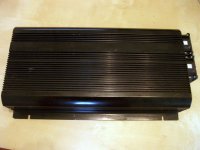
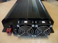
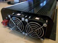
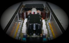
The case comes from a 12>220V inverter.
This amp as well as its bigger - stereo version, took me 3 months just for the layout.
The case comes from a 12>220V inverter.
Attachments
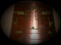
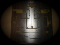
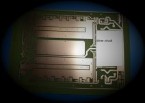
the dimensions of the hand made pcbs were tailored to the internal size of the case.
The pcbs come from photo sensitive Presensitized boards.
Then, i used liquid tinn and a special laquer to protect the uderside of the board
The pcbs come from photo sensitive Presensitized boards.
Then, i used liquid tinn and a special laquer to protect the uderside of the board
Attachments
Last edited:
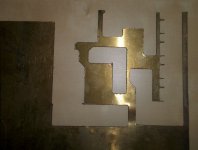
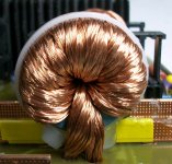
One of the main goals was to keep the resistance of the circuit as low as
possible
due to the high currents that flow.
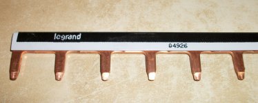
In the past i have used brass sheets, cut in a cnc machine to strenghten the
high current areas of the board.
This time i thought of busbars. Actually, not custom made, but the type readily
available to market.
possible
due to the high currents that flow.
In the past i have used brass sheets, cut in a cnc machine to strenghten the
high current areas of the board.
This time i thought of busbars. Actually, not custom made, but the type readily
available to market.
Attachments
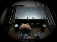
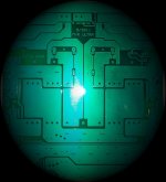
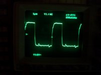
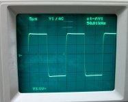
The difference from other pwm is the high oscillating frequency.
Although this is a typical push pull designs, it took me 4 versions to implement
the fast gate drive circuit.
The control is made of smd parts and it is a small board perpendicularly attached
to the main board.
The pic shows the gate drivers at 240KHz.
Although this is a typical push pull designs, it took me 4 versions to implement
the fast gate drive circuit.
The control is made of smd parts and it is a small board perpendicularly attached
to the main board.
The pic shows the gate drivers at 240KHz.
Attachments
this amp is class A /AB/D?
this is a AB hign fidelity amp.
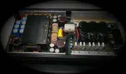
the input choke is calculated for 150A.
Both trafos are calculated for the same current,
and the secondary winding is 12A per rail.
After the double full bridge circuit, there are two cmc chokes
and a big capacitance bank.
The secondary is isolated from the primary side.
Both trafos are calculated for the same current,
and the secondary winding is 12A per rail.
After the double full bridge circuit, there are two cmc chokes
and a big capacitance bank.
The secondary is isolated from the primary side.
Attachments
That is a very nice piece - my complements. Lots of clever mechanical solutions. Also your gate drives are symetrical with very little ringing.
Thank you for your comments.
Actually, i did went up to 400KHz, but for safety reasons i changed it.
Attachments
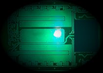
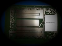
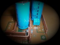
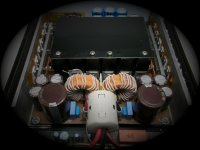
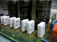
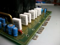
There are 6 high ripple 3300/100V capacitors, used as bypass to the output mosfets.
The trafos are shielded with a mu metal sheet, as well as the driveer circuit of
the audio amp.
Two following pics are from the older version pwm (sorry dont have any newer)
The trafos are shielded with a mu metal sheet, as well as the driveer circuit of
the audio amp.
Two following pics are from the older version pwm (sorry dont have any newer)
Attachments
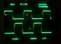
results
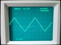
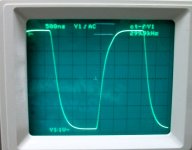
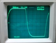
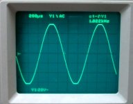
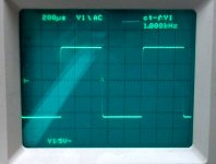
Two things describe this amp :
Speed and bandwidth.
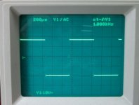
Both pics are taken with the amp fed with 4Ω/1% resistive load, at 37Vp-p.
The small overshoot at the square, dissapeared with a different setting of the
idle current.
Two things describe this amp :
Speed and bandwidth.
Both pics are taken with the amp fed with 4Ω/1% resistive load, at 37Vp-p.
The small overshoot at the square, dissapeared with a different setting of the
idle current.
Attachments
power
The output power with a 4Ω load (unclipped) was 119Vp-p (442Wrms/4Ω)
and it reached 123Vp-p (475Wrms 4Ω at clipping).
Efficiency was measured at 410Wrms/4Ω, and was about 56%.
I cant be more specific, as my ammeter is not that accurate (for now)
At 2Ω load the output at clipping was 37.5V, resulting in 703 Wrms.
The consumption was around 110A, therefore Efficiency was about 47%.
Attachments
Last edited:
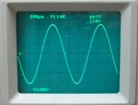
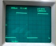
In a Greek forum where this amp was presented, i was asked to provide photos
of the amp driving a resistive load with a capacitor in parallel.
First pic is 4Ω with 2,2μF in parallel
second pic is 4Ω with 4,7μF in parallel
of the amp driving a resistive load with a capacitor in parallel.
First pic is 4Ω with 2,2μF in parallel
second pic is 4Ω with 4,7μF in parallel
Attachments
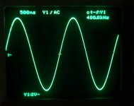
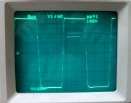
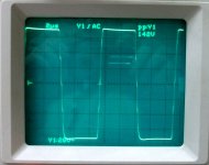
For me, i think that the best way to test the stability of the amp
-especially when mosfets are used to the output-
is to drive the amp with a high frequency square signal, unloaded.
The two pics below, show the same event.
In the frist one we see the 100K square frequency,
and when i changed the setting of my scope we see that this is 142Vp-p.
In my opinion, not all mosfet amps are capable of this.
Attachments
")
- Status
- This old topic is closed. If you want to reopen this topic, contact a moderator using the "Report Post" button.
- Home
- General Interest
- Car Audio
- Diy monoblock 700Wrms/2Ω