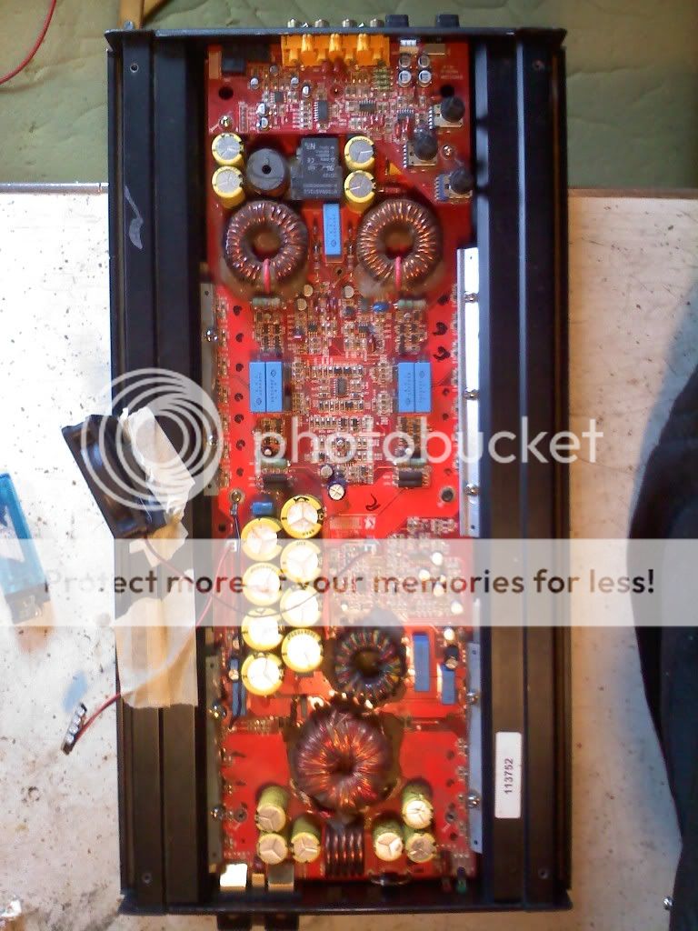
i have a kx1200.1. a couple years ago i blew a sub powered by this amp. after sub blew amp blew as well. . so, i tested here n there with dmm. i ended up having some of output and power supply transistors blown. and a couple gate resistors.
so. i changed all the transistors and gate resistors with new replacements exact match of what was in. and tested again, everything looks good. but im, kinda of, new to repairing.. ive been trying for years and have only recently had any luck.
when i tried to power it up after repairing the parts i cannot get anything from amp. no power no protection light. nothing.
i wanted to ask on here if someone could give me some advice on what to check for . im trying to figure out what to check to find out why it wont power up. i figured at least it would power and possibly blow somthing else maybe or work . but it does nothing. wiring is good , i have other amps that work fine on wires
can someone tell me what i should check for power into amp
ok. i am reading up nowon how to convert pc power supply into 12v supply , as that is my only option to power my amps to test ,besides running back and forth to car or bring battery inside. i dont want to do that as i am constantly working on amplifiers. as soon as i can get that made i will test and post my voltages. thank you for your help. perry you are awesome. thank you so much for the knowledge you share.
You don't need to do anything to make the power supply produce 12v, except maybe load the 3.3 or 5v output. Connecting the green and black wires on an ATX power supply will make the supply turn on and have output from all pins. The only real advantage of modifying one is that you'll have a bit more voltage and a bit more stable voltage.
thanks for the info . the power supply i had around says hipro. says 12v at 8 amps. dont know how it compares to atx but colors match the site that i am following instruction on. all i really want to do with it is make it a useable 12v source for powering up amps and decks to test basicly . dont need it to do anything else. but site i was on called it modifying to use as bench power supply. so kinda how i said it.probably will have it done tomarrow and then will be able to use it and test im hoping. will post my results asap
ok. i got the power supply finished. i checked it over and tested it a few times just to be sure i didnt make any mistakes . i also tested a couple good amps to make sure it worked correctly. works great.
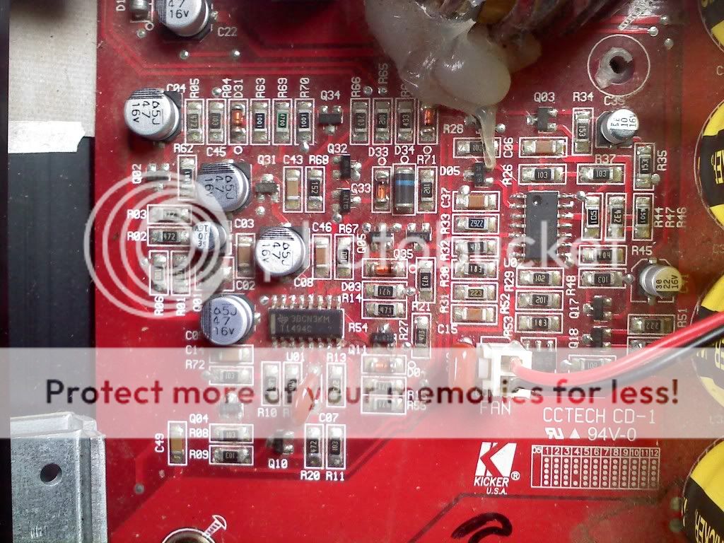
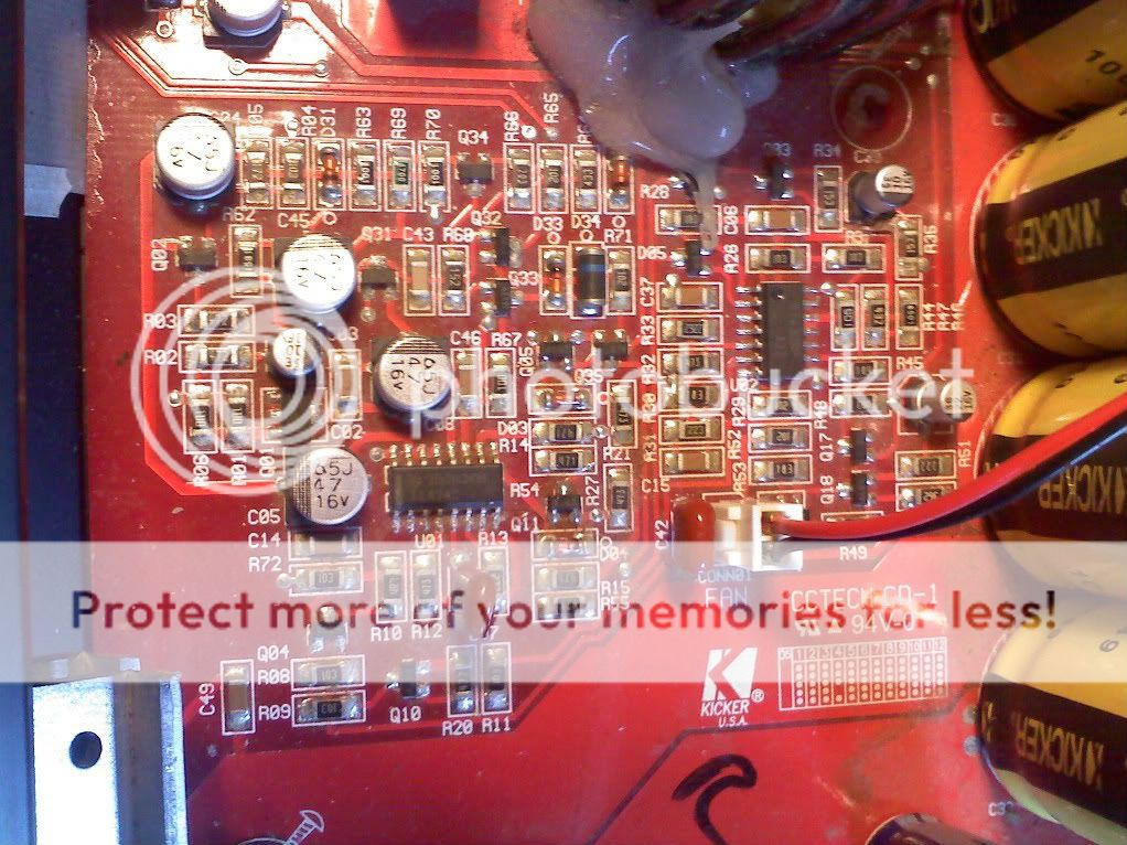
now . i hooked up kicker 1200.1 to it. i jumped the remote wire from 12v . .i get " 0v " on every pin on the tl494c.
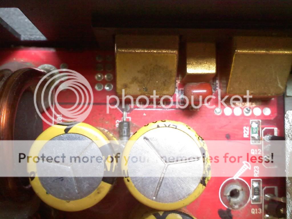
i checked with dmm . at b+ terminal on amp , i get 11.82 volts ,which is what the ps puts out at its b+ terminal with fan,(without fan it puts out around 12.08v. ) on circuit board i get the 11.82 volts on the b+ circuit... it goes from that part of circuit to a diode?? I THINK ITS A DIODE( D01 LOCATION ON BOARD) on the side of that (d01) that is in contact with b+ circuit i get the 11.82v, but when i put dmm on the opposite side of (d01) i get nothing. i was thinking it may be a 1 direction diode that has blown possibly?? but i dont know becouse i am unsure of how to test that component...
also directly off of the same b+ circuit but on the other side nerer to ground there is a component (co1 location on board) that is same ... it tests 11.82 on the b+ side of this component but ov on the other side so maybe that (c01) is blown?? i am unsure of this
i put the 12v into amp but seems to stop right about b+ terminal on amp. any ideas would be VERY APPRECIATED.
now . i hooked up kicker 1200.1 to it. i jumped the remote wire from 12v . .i get " 0v " on every pin on the tl494c.
i checked with dmm . at b+ terminal on amp , i get 11.82 volts ,which is what the ps puts out at its b+ terminal with fan,(without fan it puts out around 12.08v. ) on circuit board i get the 11.82 volts on the b+ circuit... it goes from that part of circuit to a diode?? I THINK ITS A DIODE( D01 LOCATION ON BOARD) on the side of that (d01) that is in contact with b+ circuit i get the 11.82v, but when i put dmm on the opposite side of (d01) i get nothing. i was thinking it may be a 1 direction diode that has blown possibly?? but i dont know becouse i am unsure of how to test that component...
also directly off of the same b+ circuit but on the other side nerer to ground there is a component (co1 location on board) that is same ... it tests 11.82 on the b+ side of this component but ov on the other side so maybe that (c01) is blown?? i am unsure of this
i put the 12v into amp but seems to stop right about b+ terminal on amp. any ideas would be VERY APPRECIATED.
posetive . i jumped it from the b+ to remote.. does everything u have had me check seem to test ok . . is there a component i can check in the remote circuit that u can think of off the top of your head that may be reason for possibly remote not turning amp on. i have also re checked the tl494 just to see if my testing was correct the first time i did, and i still get 0v on all legs
do u think that q02 is blown . i trace 12v from q01 to q02 . 12v goes into q02 and it stops, maybe that is what it is sopposed to do. but i do not know. i trace 12v from the remote wire to do2 , which is pretty much between 2 capacitors c12 and c13. . but from there i think it goes to bottom side of board and i do not know wher to check for remote power after that point. i know the remote gets 12v up to do2.
also i checked voltage on the middle leg of what "i think" are the,power supply transistors , irf3205 and i get 12v on them all(q06, q07, q09, q09-q12, q13, q14 ,q15)
also i checked voltage on the middle leg of what "i think" are the,power supply transistors , irf3205 and i get 12v on them all(q06, q07, q09, q09-q12, q13, q14 ,q15)
An externally hosted image should be here but it was not working when we last tested it.
i can take pics of anything if it will help you. possibly going to take amp back apart again to look at circuit on bottom that i cant see with it put together. . when i do that im gonna do a photo shoot of the board. another thing. sorry for the dirty pictures , there is a noticable amount of dust on board , could be wiped off but was just blown off and not wiped. and in a couple of the pictures of the caps u can see some plastic melted some. that is just from me having iron to close
Last edited:
- Status
- This old topic is closed. If you want to reopen this topic, contact a moderator using the "Report Post" button.
- Home
- General Interest
- Car Audio
- another kicker kx1200.1