So, first off i want to thank diy audio, Perry Babin, and bcae for teaching me literally everything i know.
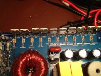
So, this amp that i got for FREE had all its output transistors ( i think, near the transformer, removed in the picture) showing 0 to 1 ohm over every combo of legs. There was black mars from three of them and two were cracked in half.
now, the other side of the board, one row of the mosfets they all show around 900 ohms. The other row all read EXACTLY 20 ohms. are they all bad? or is there something else wrong making them all show the same thing?
I searched diy for this amp and nothing came up, i have the HFI1000d and couldn't find that either.
i repaired 2 of my amps but those both required simply replacing 2 transistors so i'm in over my head right now.
thank you guys for the awesome forum!!
Attachments
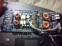
The output transistors are the ones on the left in the photo. The FETs missing from the board are the power supply transistors.
You need to remove all of the power supply transistors on the side where the cracked ones were and then re-check what's in the board.
You'll need to replace all of the ones in the group with the ones that cracked.
You need to remove all of the power supply transistors on the side where the cracked ones were and then re-check what's in the board.
You'll need to replace all of the ones in the group with the ones that cracked.
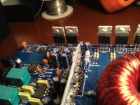
So, the resistors going to the shorted components, (which were IRFP064N, 6 per side)(shown in blue on the picture) all showed what they were labeled: (47ohm) does this mean i still need to replace? will they not perform under current?
The resistors for the green and red components seem good (compared to each other and their markings)
the transistors labeled in green and red:
There are 5 of each kind in a single row, to total ten per side, 20 overall. the 5 near the blue lines: have sort of a script/logo/bold "F" followed by 10344. the other 5 towards the purple dots have the same "F" followed by M0351. i had some trouble finding the parts online, any substitutes?
pic 2: i re-checked the row labeled with green and found i only had resistance with one leg. 900ohms with the red lines 0 with the light blue. i assume i need to replace all 20. (the row in red all near 0 ohm)
are the "drive transistors" the ones i labeled green and red?
Perry, "then re-check what's in the board. " I'm sorry, i'm not really sure what you mean by this. the rest of the transistors? or where the transistors i removed were?
Finally, the purple dots are IC's i belive, TL075CN should i troubleshoot these at all?
THANK YOU
Attachments

If the resistors are within the tolerance indicated by their markings, they don't need to be replaced.
TL072s are op-amps.
The green and red transistors are the output transistors.
Do you read exactly 0 ohms for all of the output transistors from pin 1-2?
What is the value of the gate resistors for the output transistors?
TL072s are op-amps.
The green and red transistors are the output transistors.
Do you read exactly 0 ohms for all of the output transistors from pin 1-2?
What is the value of the gate resistors for the output transistors?
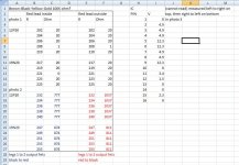
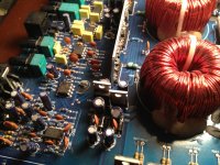
Below is a screenshot of an excel sheet with gate resistor values and markings. Along with IC volts.
Corresponding photos are given.
I don't know why my multimeter reads (in "ohm mode") differently when reversed
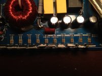
Are the gate transistors the two stand-alone guys in photo 3? Do i test these on diode check? I will definitely replace them anyways. In photo 4 there are the same pair. What are these guys?
The amp gives the power light with no protection light. The relay seems to switch okay.
New question:
I hooked this up to a small 12v wheelchair battery on a 10A fuse.
When i put it to check DC amps the fuse blew.
I didn't know what to make of it so i tried it again with a 5A after it came on and did not read any Amperage, the fuse remained intact.
I took out my HFI1000D (power transistors removed like the 2500D) and tried the same and it read a bit of current before it blew the fuse (leads connected before start-up)
Should i not be trying to read the current draw?
Thank you guys
Corresponding photos are given.
I don't know why my multimeter reads (in "ohm mode") differently when reversed
Are the gate transistors the two stand-alone guys in photo 3? Do i test these on diode check? I will definitely replace them anyways. In photo 4 there are the same pair. What are these guys?
The amp gives the power light with no protection light. The relay seems to switch okay.
New question:
I hooked this up to a small 12v wheelchair battery on a 10A fuse.
When i put it to check DC amps the fuse blew.
I didn't know what to make of it so i tried it again with a 5A after it came on and did not read any Amperage, the fuse remained intact.
I took out my HFI1000D (power transistors removed like the 2500D) and tried the same and it read a bit of current before it blew the fuse (leads connected before start-up)
Should i not be trying to read the current draw?
Thank you guys
Attachments
Last edited:
There is no component on the board that's referred to as a gate transistor.
The components are likely regulators. You can look up the part numbers on the face of the components. That will tell you what they are.
Any output transistor that reads 0 ohms between any two legs is likely defective or is in parallel with a defective transistor. Since you measured between 1 and 2, the ones that read well under 20 ohms is likely defective.
- Status
- This old topic is closed. If you want to reopen this topic, contact a moderator using the "Report Post" button.
- Home
- General Interest
- Car Audio
- Basic repair question for HFI2500d