Am currently working on a SS 700sx. When I first got it, it had Q55 & Q59 blown up and three resistors that were toasted (R135, R190, R171). So I checked the output transistors (TIP102 & TIP107) and seemed like there were also bad. I also had to replace two transistors Q47 & Q49 because I broke them off of the board.
So I replace all those parts with new ones. The Q47 & Q49 were also replace with new ones (dont know if I should of replaced all of them Q47-Q52, or if it matters).
I placed board back in chassis and tightly screwed all the transistor clamps. I powered it up and it played but very low and distorted, then after 10 seconds I could smell smoke and cut it off right away (I believe I used a 15amp fuse when I powered it up). Opened it up and again Q55 & Q59 both where blown completely and when I checked the TIP102's & 107's and 12 of them where shorted (Q25,26,27,28,41,43,29,30,31,32,42,44) so I removed all 12 of them and now have no clue what to do.
Am afraid that if I replace those 12 TIP transistors the same will happen (and their not cheap) not to mention the Q55-MPS8599 is no longer in mousers warehouse and I only have one left.
What should I check?
Last edited:
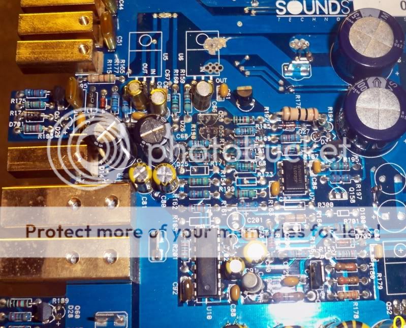
Q59 is the amps protection device for the right channel and is tied to the emitter resistor and the output to detect DC voltage drop which must be present in huge amounts by the failures your telling us about.
Q55 is the transistor just after that is used to combine both Q59 and Q56's output back to U7A a TLO-72 op-amps that seems to control high or low current operations leds and interface to the PWM controller.
It is likely that the FEB driver board has failed, it can be repaired and possibly replaced new thru Jaime at jandrelectronix@aol.com. This along with all the outputs replacement should bring that channel back to life. A simple DC voltage check across the speaker terminals will tell weather or not the transistors Q55 and Q59 will burn up again. But this would be doubtful with the entire channel repaired with new outputs and a new or repaired FEB driver board.
Oh I would also check each individual emitter resistor as they like to burn open on failures like this and they also must be in spec to get the channel repaired. And once the channel is repaired a simple voltage drop measurement across each emitter resistor will tell you if you have any mismatched output transistors that need to be removed and replaced with better matching devices. < this is how SS repaired these amps so I would follow this last step carefully IMHO >... Hope this helps some..")
PS: You said the amp turns on and play at very low levels on the one channel that is still intact. This makes me think it also has issues perhaps some DC voltage on its speaker terminals also. I would also check all of those outputs in that channel and all of their respective emitter resistors. I have seen people run these amps into submission on subs before and both channels were badly damaged. Hope that is not the case for you here but with the info you listed it sounds like both channels may be damaged not just one...
Q55 is the transistor just after that is used to combine both Q59 and Q56's output back to U7A a TLO-72 op-amps that seems to control high or low current operations leds and interface to the PWM controller.
It is likely that the FEB driver board has failed, it can be repaired and possibly replaced new thru Jaime at jandrelectronix@aol.com. This along with all the outputs replacement should bring that channel back to life. A simple DC voltage check across the speaker terminals will tell weather or not the transistors Q55 and Q59 will burn up again. But this would be doubtful with the entire channel repaired with new outputs and a new or repaired FEB driver board.
Oh I would also check each individual emitter resistor as they like to burn open on failures like this and they also must be in spec to get the channel repaired. And once the channel is repaired a simple voltage drop measurement across each emitter resistor will tell you if you have any mismatched output transistors that need to be removed and replaced with better matching devices. < this is how SS repaired these amps so I would follow this last step carefully IMHO >... Hope this helps some..
PS: You said the amp turns on and play at very low levels on the one channel that is still intact. This makes me think it also has issues perhaps some DC voltage on its speaker terminals also. I would also check all of those outputs in that channel and all of their respective emitter resistors. I have seen people run these amps into submission on subs before and both channels were badly damaged. Hope that is not the case for you here but with the info you listed it sounds like both channels may be damaged not just one...
Last edited:
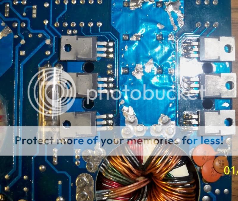
You also said you replace two of the 6 mosfets in the power supply. Have you checked the rail voltages to the outputs? The side of the supply you replaced the mosfets in may still not be functional even with new mosfets and the rails will be much lower then required for the amp to work properly.
When these fets blow they often take out the gate resistors 3.3 ohm and the gate drivers Q54 and Q46. If this is the case the supply will only have half functionality, and the new fets installed will burn up in most cases due to self enhancement....
When these fets blow they often take out the gate resistors 3.3 ohm and the gate drivers Q54 and Q46. If this is the case the supply will only have half functionality, and the new fets installed will burn up in most cases due to self enhancement....
I buy my tip102/107 from mouser since their close to me (14miles away) but I might have to try arrow, mouser want 1.50 each for STP or TI.
I have not powered up the amplifier since Q55 and Q59 are out of the board, or could I try powering it up to see if I get power from the right channel?
I powered it up once I replaced all 24 TIP102/107 transistors and it played but I believe it was both channels that were distorted (unless my dumbass run it bridge, then there's no way to tell which channel was distored and low).
If the FEB board fail how could I check it or should I replace all the parts on it? If its cheap I rather pick one up from jandrelectronics.
You also said you replace two of the 6 mosfets in the power supply. Have you checked the rail voltages to the outputs? The side of the supply you replaced the mosfets in may still not be functional even with new mosfets and the rails will be much lower then required for the amp to work properly.
When these fets blow they often take out the gate resistors 3.3 ohm and the gate drivers Q54 and Q46. If this is the case the supply will only have half functionality, and the new fets installed will burn up in most cases due to self enhancement....
yeah i replace just two because I broke them off accidently. I purchased them new and never thought if it matter or not if they were mismatched, I know the tip102/107 all have to be from the same run/manufacture date.
So your saying put the board back in chassis, and check rail voltage? What should it be at?
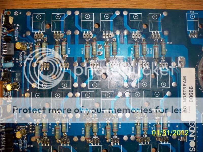
Are the emitter resistors on the board correct? On schematics it calls for .27 2watt but on the board it looks like red, violet, gray then gold which means 2,700,000k ohms LOL am I right or wrong? They look like they were replaced at one time but looks very proffesionaly could pass for factory.
edit: LOL okay I looked around for gut pics and looks like those are correct resistors.
edit: LOL okay I looked around for gut pics and looks like those are correct resistors.
Last edited:
Are the emitter resistors on the board correct? On schematics it calls for .27 2watt but on the board it looks like red, violet, gray then gold which means 2,700,000k ohms LOL am I right or wrong? They look like they were replaced at one time but looks very proffesionaly could pass for factory.
edit: LOL okay I looked around for gut pics and looks like those are correct resistors.
The emitter resistors are the correct ones for the amp. I would check each of them to make sure they are all in spec. As I said before they blow open like fuses do when the outputs short out.
Jaime can usually supply you a new FEB board, and all the parts used on them if you want to repair the FEB. I would email him and see what he has on hand and go from their. It is quicker just to replace the FEB if he still them in stock, and since you plate is full repairing this amp perhaps the cost of new FEB's would be offset in time savings. Chances are that both boards are defective at this point.
I'll get two from him, keeping my fingers cross and hopefully he as two or can let me know how to test them.
This amp is a real PITA, am repaired a few amps (5002, JL 500/1, kicker dx700, xt1600.2, a flat screen with a blown power supply, even a remote control for a new car lol) so am kinda experience, just wish I could learn more and more.
Thanks guys for the help, I'll keep ya'll posted if JandR come through.
1moreamp- what exactly is the value of those resistors? Because I doubt their 2,700,000k ohm more like .27ohm right? Because on board they read about .8ohm and I understand I cannot test them on board becasue of the way their in circuit. I'll remove them later on today (am away from the pc right now) and post results later today. Thanks.
Last edited:
the bands would be red-purple-silver-gold. it's a pita sometimes when they have seen heat over time. i've tried all different kinds of bench spot lighting to read old resistors better. right now the halogen35 seems to be doing ok. anyways, i would start by pulling the 2 driver boards and checking the circuits on them. chances are the drivers are damaged. it looks to use the same as the 500, where the 1000 needed to have some paralleled on the board. it's also nice to make sure the mounting connections are fresh for the driver boards. also, check q35 and q21 for damage as mentioned, all that q59 does is activate with a big enough voltage drop across one gate resistor, then 55 is tied to both 55/56 and (+) rail voltage, then run through a resistor and diode to the (+) lower regulated voltage. i would check all those parts for damage
Thanks for the info.
The boards (both FEB and pre-amp) look like they have solid good connections. Is there any way to check them? Or what usually goes bad on them? I hate smd compenents but have work with them in the past with no problems, just a PITA when you have to make sure the SMD parts dont move with the touch of the iron, lol.
The boards (both FEB and pre-amp) look like they have solid good connections. Is there any way to check them? Or what usually goes bad on them? I hate smd compenents but have work with them in the past with no problems, just a PITA when you have to make sure the SMD parts dont move with the touch of the iron, lol.
i used my fine tiped leads and did a contiuity check from one end of the solder on the preamp board to the other end of the connection on the main board. i could not really even see the broken connections, but i was able to see tiny lines when looking real close. if you pull the preamp boards, you can isolate more of the circuits and components from each-other.
Checked the emitter resistors and they all read 0.4ohms. Then i checked Q56 and it was BAD, it looks perfectly fine but after testing it it was bad also. So now am worried if both channels were bad after repairs.
Then I checked one transistor (Q37) and the collector pin wasn't making proper contact, wasn't solder properly (by me, what a dumbass, lol).
So now my question is should I just go ahead and replace all the TIP102/107 on the Right channel (the ones I left on the board)?
Darn it I should of just sold this amp for parts a long time ago, spend 24 bucks on transistors already plus a few resistors and now it looks like another 20 bucks in parts. Next time I know if i purchase a broken amp I better get it real cheap otherwise pass on it.
lol, tell me about it, i spent $75 on an order of 50ea. 107/2's i really like these amps, though. did that diode check out ok? you should be able to leave the q56 out of the circuit for testing the right channel for problems. the circuit should run from the left channel just fine. check for shorting on pins 5;6;7 on the tl072. the q56 was likely just damaged when q55 went out. if the right channel outputs read fine, i wouldn't worry about replacing them just yet.
*couple typos on my post #11 "check q35 and q21 for damage. as mentioned," "across one gate resistor, then 59 is tied to both 55/56 and (+) rail" fixed
*couple typos on my post #11 "check q35 and q21 for damage. as mentioned," "across one gate resistor, then 59 is tied to both 55/56 and (+) rail" fixed
I just got my 700s back operational today. Changed a lot of parts- PS fets, driver trans, gate res, rectifiers, and a controller IC. I got my parts from Jaime- great guy. And much thanks to Perry for his tutorial and spot on e-mail advice. I bought spare parts & some parts I turned out not needing but good to have as I have several of these old Soundstreams. I'm not doing this to save money- I enjoy knowing I fixed it myself and learning about these amps. I think I have read everything on this forum about these amps- at least what I can find by searching. There is an awesome amount of information on here that I am grateful for also.
good deal man.... if you ever want to do a deal on some, i'm always interested. i guess you could say i had the kicker zr's, ssref's, and then directeds imprint on me about what real clean/solid power is. i even have my original 1000sx sitting on the bench, and i sold it a year or so after buying it brand new. i still have tons to learn myself, and more equipment to buy to get set up, but i'll learn every circuit in these amps by heart if it kills me, lol, and yes, perry is an awesome wealth of knowledge. lives and breathes this stuff, and never wants anything back.
I'm also a do-it-yourself type of guy. But ofcourse need some help on the way. Perry has helped me a lot, I have his tutorial also and very grateful. We'll see if Arrow allows me to register so I can get the tip102/107's real cheap, 24 would cost me about 28 bucks at mouser and at Arrow 24 for 8 bucks thats crazy.
- Status
- This old topic is closed. If you want to reopen this topic, contact a moderator using the "Report Post" button.
- Home
- General Interest
- Car Audio
- SoundStream 700sx w/bad transistors