Hey, new guy here looking for a little help with a PPI PC1400.
I'm new to electronics, but I want to fix my PPI PC1400.
I want to start out by replacing the visually damaged and missing parts.
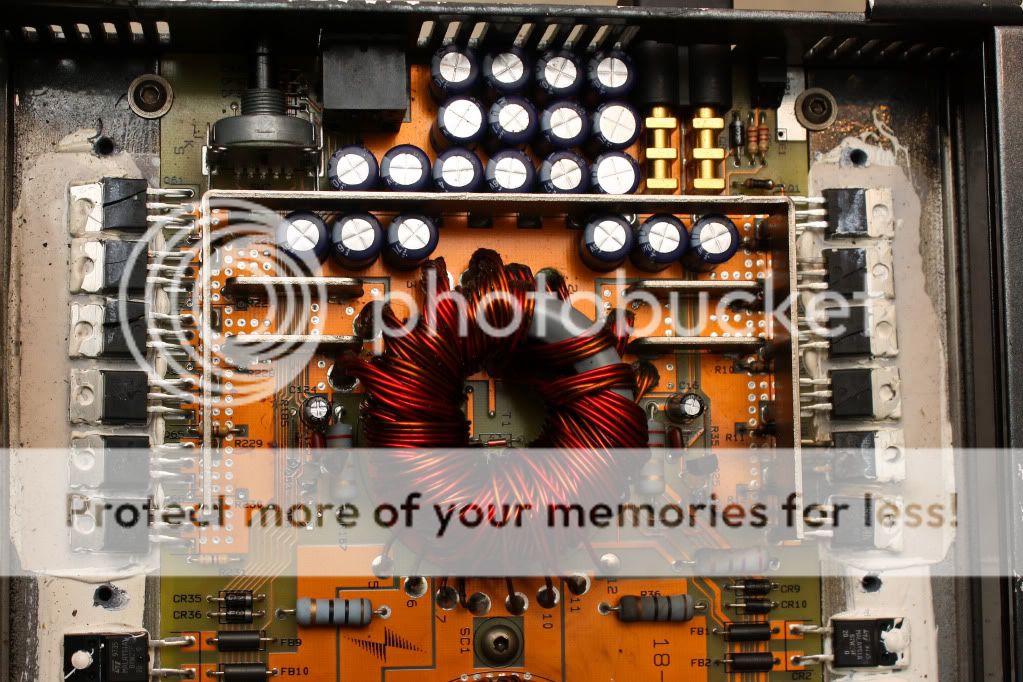
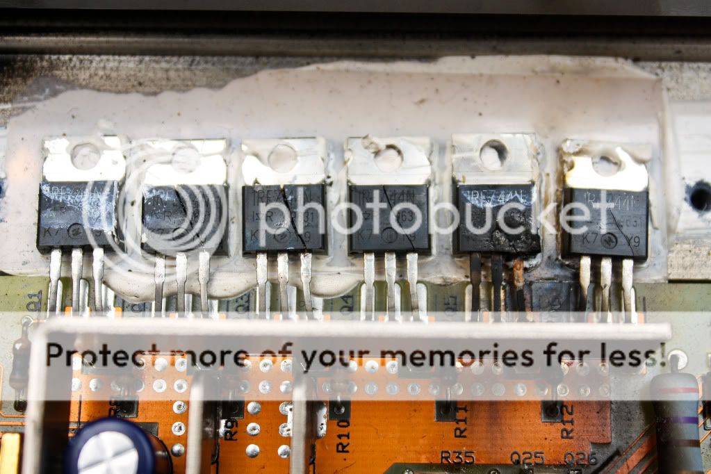
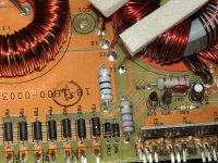
From what I can SEE, this is what I'm dealing with. All damage is on the POWER side.
Blown:
9 IRFZ44 FETs (Non matching. Indicative of previous repair?)
9 resistors ( R7 R8 R9 R10 R11 R12 R36 R78 R167)
2 transistors ( Q25 Q53 )
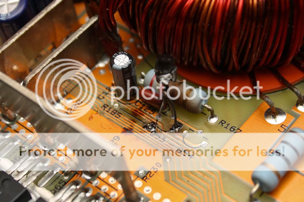
2 capacitors ( C27 C125 )
Missing:
2 resistors (R35 R185 )
1 transistor ( Q26 )
I've been doing alot of research into fixing it, but I need a little bit of direction from experienced people.
If anybody could help, it would be most appreciated.
Thanks
I'm new to electronics, but I want to fix my PPI PC1400.
I want to start out by replacing the visually damaged and missing parts.
From what I can SEE, this is what I'm dealing with. All damage is on the POWER side.
Blown:
9 IRFZ44 FETs (Non matching. Indicative of previous repair?)
9 resistors ( R7 R8 R9 R10 R11 R12 R36 R78 R167)
2 transistors ( Q25 Q53 )
2 capacitors ( C27 C125 )
Missing:
2 resistors (R35 R185 )
1 transistor ( Q26 )
I've been doing alot of research into fixing it, but I need a little bit of direction from experienced people.
If anybody could help, it would be most appreciated.
Thanks
Power supplies rarely burn themselves out without there being serious issues on the audio side. By serious I mean blown outputs, blown regulators for the lower rails, bad caps, blown rectifiers, etc... The list can be endless and only teching it out with a ohm meter will get you the unknowns that may be lurking further into the repair.
Since you are new, may I suggest you look at any of Perry Babin's posts and click on his links below his posts. His links will take you to his training web-sight and there you can learn at your own pace many of the facets of the repair world. I can not stress enough how valuable his web-site will be to you in your efforts.
With his info in mind and on access to you the other details will come much easier, especially when any of us here start answering your questions that you post.
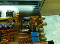
If I am not mistaken your PC1400 is also the same as the PC1800 which was a one year model later when they changed over to 2 ohm power levels instead of 4 ohm power levels. Posting some internal and external pics would be very helpful, since this amp is fairly old school. Some of us need pics to jog our memories back, Me being one of them...lol..")
All of the parts numbers you have listed are for the mosfets and their drivers and the RC filters across the toroid < the caps C27 and C125 are 0.1 ufd film type caps 50 or 63 volt most likely >. The stock mosfets were IRFZ-44 you can use IRFZ44, 46, or 48 as replacements. The fet gate driver transistors are a NPN and PNP pair, and the current limits attached to them R35 and R185 are not listed on any info I have but are likely something around 10 to 22 ohms. Again a internal pic would be helpful...
Since you are new, may I suggest you look at any of Perry Babin's posts and click on his links below his posts. His links will take you to his training web-sight and there you can learn at your own pace many of the facets of the repair world. I can not stress enough how valuable his web-site will be to you in your efforts.
With his info in mind and on access to you the other details will come much easier, especially when any of us here start answering your questions that you post.
If I am not mistaken your PC1400 is also the same as the PC1800 which was a one year model later when they changed over to 2 ohm power levels instead of 4 ohm power levels. Posting some internal and external pics would be very helpful, since this amp is fairly old school. Some of us need pics to jog our memories back, Me being one of them...lol..
All of the parts numbers you have listed are for the mosfets and their drivers and the RC filters across the toroid < the caps C27 and C125 are 0.1 ufd film type caps 50 or 63 volt most likely >. The stock mosfets were IRFZ-44 you can use IRFZ44, 46, or 48 as replacements. The fet gate driver transistors are a NPN and PNP pair, and the current limits attached to them R35 and R185 are not listed on any info I have but are likely something around 10 to 22 ohms. Again a internal pic would be helpful...
Last edited:
Well Perry sent me some pics I have uploaded to compare with. I will do a detailed parts list from your list and pics in my next post shortly...
I still think you need to ohm meter test all the outputs and rectifiers to make sure they were not the cause of this failure symptom. Perry's site has detailed steps on how to do those things. Please check his site while I figure out your parts list BOM...thx
I still think you need to ohm meter test all the outputs and rectifiers to make sure they were not the cause of this failure symptom. Perry's site has detailed steps on how to do those things. Please check his site while I figure out your parts list BOM...thx
Attachments
Last edited:
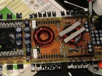
here is your BOM of parts based on your pics :
12 each IRFZ-44N or 46N or 48N any of these will work. Q1 thru Q6 and Q61 thru Q66
12 each 47 Ohm 1/4 of 1/8 watt 5% tolerance gate resistors. R7 thru R12 and R226 thru R231 1/8 watt is smaller but will not cause any issues
2 each MPSA06 Gate driver transistors Q25 and Q54 Mind the lead placement the board has orientation marks to follow
2 each MPSA56 Gate driver transistors Q26 and Q53 Mind the lead placement the board has orientation marks to follow
1 each SG3525A PWM controller chip U5
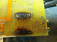
All of the other components appear to be simply soot covered. A simple wash with acetone and alcohol should clean that soot off of them. Q-tips and or tissue wetted with either solvent will clean all of the soot off the board. If they look heat stressed and soot covered clean and verify they proper value and meter them to make sure they are intact and at spec. And please clean up the board by removing as much of the soot as possible, this will help you loads.
With the level of damage you have you might need to replace the PWM controller chip U5 . It is a SG3525A. These are fairly economical and easy to find. I suggest you order one and replace it to be on the safe side since your pretty much completely replacing all of the rest of the power supply anyway. I have seen them be damaged with this level of melt down, so better safe then sorry I say, and completely rebuild the supply including the PWM controller.
C27 and C125 seem to be covered with soot and not really damaged. I would clean them and meter them to check for proper tolerance.
R35 and R185 need to be metered and read to check that they are in tolerance before replacement is chosen. I think they are just soot covered, but you must meter them to see if they are functional and at the correct value.
I still firmly believe your going to find other shorted transistors in the audio section of the amp. I hope I am wrong but 99% of the time one thing leads to another and this amp may have failed a channels outputs and may have not been fused properly to cause all of this.
I had a client that consistently would run this series of amp at 2 ohms mono and no fuse at all. Doing this did the same damage that I see in yours. He never asked for a warranty. He just wanted it rebuilt about every 6 months for the same failure. Around the 10th or 12th rebuild the copper traces on the board gave out to the point it was futile to repair it any longer. Seen this a bunch of times over the years...sad..
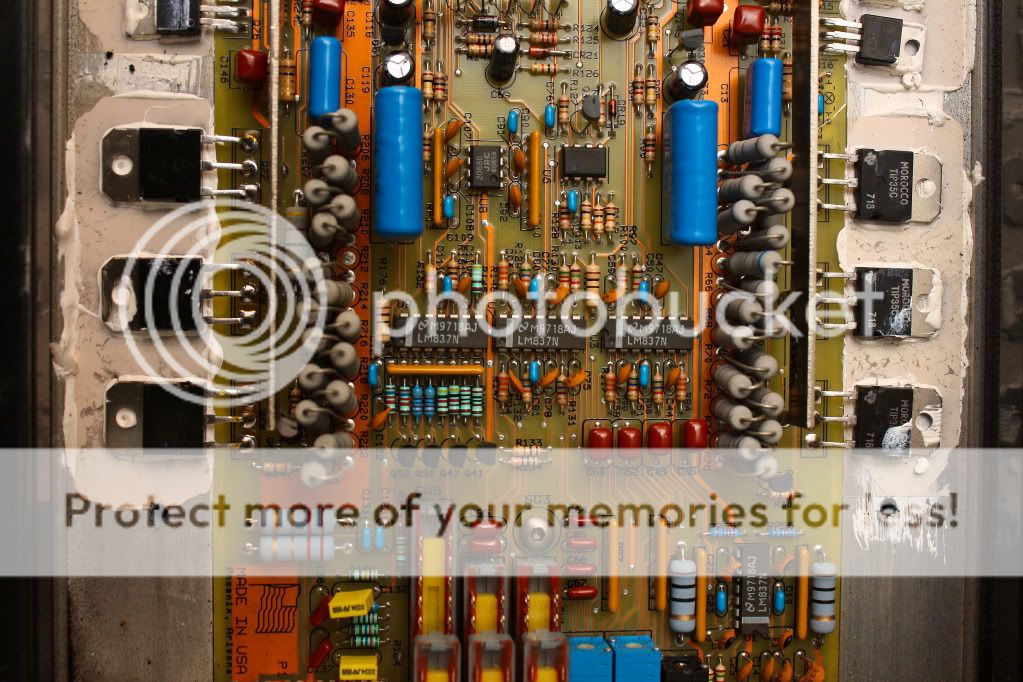
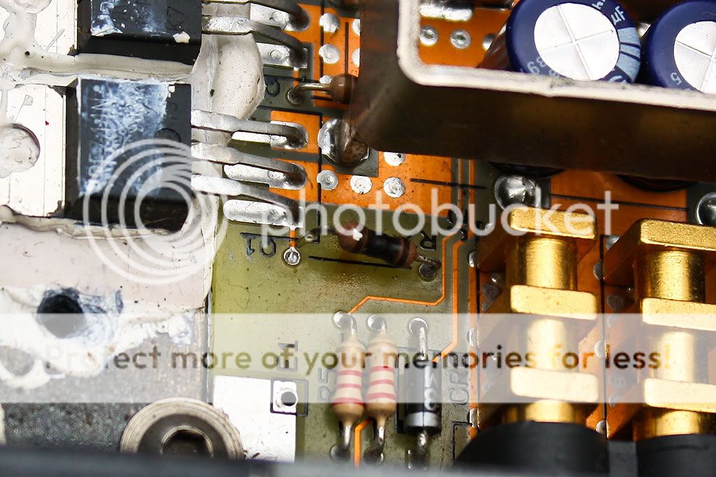
Your BOM is most likely not complete because of all the other possibilities of damaged components in the audio section. Please meter out all of the diodes and power transistors mounted on the edge of the card in the audio section. And also find and use a 5 amp inline fuse to use when first powering up the amp after all the repairs are completed. This amps should only need 5 to 7 amps to start properly and then it should idle around 1 to 1.5 amps typical. Fusing it on power up will save you rework just in case you missed something else that was defective.
AND MOST IMPORTANTLY: you must either make some bar stock clamps out of simple bar stock, or you MUST place the bottom cover of the amp back on the amp to test the amp. This amp REQUIRES the bottom to be on to clamp the power transistors in place and without it they will not be seated properly and they will fail in a split minute if the power devices are NOT properly clamped to the heatsink.
Perry shows how to use a set of bar stock clamps in his tutorial. Again I can not stress this matter enough. please build a set of home made clamps and use them while testing ANY PPI amp.
Also do not allow solvents to contact any of the metal can capacitors the solvent will remove the marking off their plastic labels. And also purchase some new heat sink compound since the new and old power devices will need fresh heat sink compound applied to them before final assembly.
12 each IRFZ-44N or 46N or 48N any of these will work. Q1 thru Q6 and Q61 thru Q66
12 each 47 Ohm 1/4 of 1/8 watt 5% tolerance gate resistors. R7 thru R12 and R226 thru R231 1/8 watt is smaller but will not cause any issues
2 each MPSA06 Gate driver transistors Q25 and Q54 Mind the lead placement the board has orientation marks to follow
2 each MPSA56 Gate driver transistors Q26 and Q53 Mind the lead placement the board has orientation marks to follow
1 each SG3525A PWM controller chip U5
All of the other components appear to be simply soot covered. A simple wash with acetone and alcohol should clean that soot off of them. Q-tips and or tissue wetted with either solvent will clean all of the soot off the board. If they look heat stressed and soot covered clean and verify they proper value and meter them to make sure they are intact and at spec. And please clean up the board by removing as much of the soot as possible, this will help you loads.
With the level of damage you have you might need to replace the PWM controller chip U5 . It is a SG3525A. These are fairly economical and easy to find. I suggest you order one and replace it to be on the safe side since your pretty much completely replacing all of the rest of the power supply anyway. I have seen them be damaged with this level of melt down, so better safe then sorry I say, and completely rebuild the supply including the PWM controller.
C27 and C125 seem to be covered with soot and not really damaged. I would clean them and meter them to check for proper tolerance.
R35 and R185 need to be metered and read to check that they are in tolerance before replacement is chosen. I think they are just soot covered, but you must meter them to see if they are functional and at the correct value.
I still firmly believe your going to find other shorted transistors in the audio section of the amp. I hope I am wrong but 99% of the time one thing leads to another and this amp may have failed a channels outputs and may have not been fused properly to cause all of this.
I had a client that consistently would run this series of amp at 2 ohms mono and no fuse at all. Doing this did the same damage that I see in yours. He never asked for a warranty. He just wanted it rebuilt about every 6 months for the same failure. Around the 10th or 12th rebuild the copper traces on the board gave out to the point it was futile to repair it any longer. Seen this a bunch of times over the years...sad..
Your BOM is most likely not complete because of all the other possibilities of damaged components in the audio section. Please meter out all of the diodes and power transistors mounted on the edge of the card in the audio section. And also find and use a 5 amp inline fuse to use when first powering up the amp after all the repairs are completed. This amps should only need 5 to 7 amps to start properly and then it should idle around 1 to 1.5 amps typical. Fusing it on power up will save you rework just in case you missed something else that was defective.
AND MOST IMPORTANTLY: you must either make some bar stock clamps out of simple bar stock, or you MUST place the bottom cover of the amp back on the amp to test the amp. This amp REQUIRES the bottom to be on to clamp the power transistors in place and without it they will not be seated properly and they will fail in a split minute if the power devices are NOT properly clamped to the heatsink.
Perry shows how to use a set of bar stock clamps in his tutorial. Again I can not stress this matter enough. please build a set of home made clamps and use them while testing ANY PPI amp.
Also do not allow solvents to contact any of the metal can capacitors the solvent will remove the marking off their plastic labels. And also purchase some new heat sink compound since the new and old power devices will need fresh heat sink compound applied to them before final assembly.
Last edited:
Ok, so...
I'm just learning how to properly meter all of the different components. The output transistors are damaged as well, just as you said.
I'm going to do some more in-depth metering tomorrow. I'm just a little confused on transistor metering. I'm also learning about amplifiers at the same time, so identifying components is mixed in there as well. I'm doing alot of research as to not ask basic questions that can be answered by a search.
By the way, thanks for the links. Those write-ups have helped alot. There's still alot more to read, but it's great information.
Thank Perry Babin, he has done a great job on his site. Hands down the best tutorial you will ever find on car amps and several other topics also. I am doubtful there are any other sites as helpful as his, IMHO.
Glad you checked the outputs. My past experience has been that power supplies don't die by themselves, and they are often only a indicator of other issues or a symptom of what really happened.
I also advise that you replace all the outputs in any bad channel in sets and not just the bad ones. The ones that still might read good are damaged and will likely fail very shortly after the amp is back in service, if it even makes it off the bench from final test.
There are other tests to be done after all the bad parts get replaced and the amp fires up without fail. I will be glad to help you thru those also, but were a ways away from that point yet. Final test before release to service is often where other minor issues are found.... Post again anytime on this thread so we can finish up your project and others can follow it to completion...as usual hope this helps some...
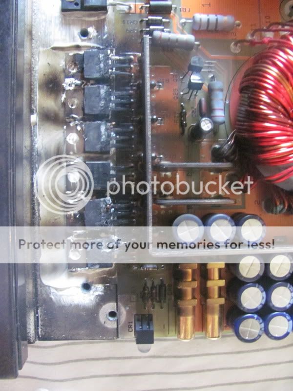
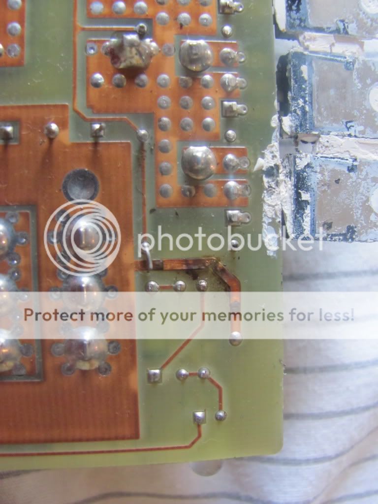
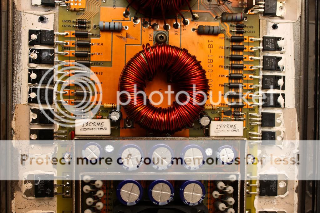
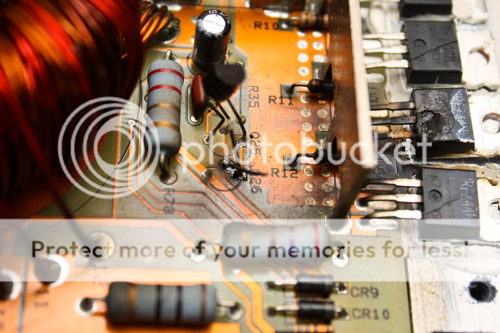
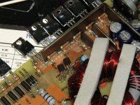
You should really start your own thread about your amp failure. Although your symptoms appear to be similar there are likely variation that need to be addressed independently. like for instance the blown ground trace in your second photo indicates that the electronics has shorted to the case in some fashion, likely thru one of the mica insulators.
- Status
- This old topic is closed. If you want to reopen this topic, contact a moderator using the "Report Post" button.
- Home
- General Interest
- Car Audio
- Help with PPI PC1400