I have an old school PPI 2150 amplifier. Black case. board says "Rev C"
Anyone have a Schematic for it?
It was playing, but would get noise once in a while. I thought it was a bad gain control, or maybe loose RCA connectors. I opened it up, and wiggled everything while it was playing. Everything seemed OK, so I turned up the volume (that is when I usually hear the noise), and the magic smoke came out!
Nothing looks burned, so I am looking for a schematic so I can figure out what I blew up.
Thanks.
If this amp uses the bottom cover to clamp the transistors to the heatsink, you can't operate it without the bottom cover tightly screwed down, unless you VERY carefully monitor the temperature of all of the transistors.
Which components failed? Give the circuit board designations for each one.
Which components failed? Give the circuit board designations for each one.
Already realize where I screwed up.. The bottom of the case keeps all of those TO220 packages against the heat sink!!
I pulled out 2 of the P25N05, and it is for the most part a short (12 ohms from S to G, .7 Ohm from S to D and 240 Ohm from S to G, 230 Ohm from S to D).
Likely that I fried all 10 of them?
Maybe the 2N6486/2N6490 parts are still OK?
Still would love a Schematic.")
I pulled out 2 of the P25N05, and it is for the most part a short (12 ohms from S to G, .7 Ohm from S to D and 240 Ohm from S to G, 230 Ohm from S to D).
Likely that I fried all 10 of them?
Maybe the 2N6486/2N6490 parts are still OK?
Still would love a Schematic.
Thanks Perry, I saw that (heat sink) too late.. Was posting that, but I think I am being moderated right now, so my posts are delayed.
There is nothing visually obviously failed. I wanted the Schematics to help diagnose.
Strange thing is, the fuse did not blow. I would have expected it to if I cooked all of the MOSFET's.
Was posting that, but I think I am being moderated right now, so my posts are delayed.There is nothing visually obviously failed. I wanted the Schematics to help diagnose.
Strange thing is, the fuse did not blow. I would have expected it to if I cooked all of the MOSFET's.
Seeing that the P25N05 is disco.. NTE has a replacement (2396), but it is way expensive (as most NTE parts are). I read in another thread that IRFZ44 is a good replacement?
Interesting that NTE lists the xref for Z44 as 2395. This is a 60V part, where the 25N05 is 50V.. More power! (grunt grunt)
Any brand better than another? buying 10 of them, cost becomes important.
Anyone use this outfit? I like the price..
IRFZ44 IRFZ44N MOSFET N-Channel 49A 55V
Newark Electronics has a few options for them.. Even a few with a 150W pd. (50A instead of 25A). Those would be less likely to pop, no?
This looks like the lowest cost in the TO220AB package from Newark;
INTERNATIONAL RECTIFIER|AUIRFZ44Z|MOSFET,N CH,55V,51A,TO220AB | Newark.com
What I am wondering is - if I blew all those MOSFET's would anything else have been taken with it? How likely is it I blew the 6486/6490's from heat too? I tested one of them with the DVM and it did the high/low thing.. so, I guess it is OK? I don't want to pull them all out if I don't have to.
Thanks for the help (and the archives of this forum).
Kept reading the thread..
http://www.diyaudio.com/forums/car-audio/48630-ppi-amp-power-precision-blew-out-11.html
I need to replace the P25N05 MOSFET's (10 of them), and see that the Z44 or Z48 have been suggested for this purpose. Do I need to change the gate resistors too? Mine look like 650 Ohm. (Blue Green Brown).
Thanks again..
You can use the IRFZ44s if the gate resistors are 100 ohms or less.
I haven't used Tayda but there have been some posts questioning the quality of the FETs sold there. If you're in the US, there are better options.
CLICK
It's possible that you did more damage. You can check most of the transistors in the circuit.
Read the basic amp repair page (link in sig line below).
P25N05 fets are used in the older 2150M as I recall, is that the amp your repairing??? If so it is possible to upgrade but you will likely have to also upgrade the gate resistor to make them work.
Try looking for IRFZ-34 as a replacement. PPI used those also without circuit modding the gate resistor.
Just about any 25 to 30 amp fet will work.
Try looking for IRFZ-34 as a replacement. PPI used those also without circuit modding the gate resistor.
Just about any 25 to 30 amp fet will work.
Z34 's were used by PPI in these very amps when the 25N05's were not available. These amps were built back when fets first hit the car audio market and parts shortages were common.
The no trouble replacement is the Z34, as I recall and the Z42,Z44,Z46, and Z48 all have lower turn on resistance and higher current handling but I don't think you will see any real benefit due the toroid design being what it is.
For me the Z34 is the best no issues choice. Simple drop in place replacement, and no need to worry about gate resistor value.
Had time to read through the the link Perry sent out. Very comprehensive, nice work.
I do have experience in working with electronics, testing components, using an oscilloscope (I have a digital storage scope), so I think I have what I need to do this myself. I have repaired audio amplifiers before, so although I may be rusty- I think I got the basics- Ignoring the fact that it is my own DUMB fault this amplifier is broken (running it with the cover off, so the heat sink did not have good contact).
I can't be the first idiot to do this, right? At this point, I'd like to place an order for the parts I will likely need. Without a schematic, frankly, I was looking for someone with experience on this particular model to suggest what else I may have blown out by running it without the cover... So I only have to place one order for parts.
10 of the Z34's will cost me only $3. But it is $8 to ship! So, if I need more parts I'd like to get them to begin with.
Thanks again.
Post a picture of the amp board. Most of us go by that when the amp is as old as yours just to jog our memory a bit about what it looks like. I have not seen one of these for at least 10 years now myself.
For what its worth always check the fet gate drivers if that amp has them. And also ohm out all your output transistors to make sure you won't power the amp back up into a dead short. Also check the rectifiers near the toroid they like to go shorted as I remember especially when you find no bad output transistors...
Other then that these amps were very simple to repair in most cases and I am thinking you will likely find it to be the same if you follow the few steps above and Perry's excellent tutorial....
I advocate shotgunning sometimes myself but only when its just plain cheaper to completely rebuild, then second guess and waste time testing individual parts, and when its financially prudent.
In your case though I would test and check prior to replacement of the power supply, and not shot gun because you might create an unknown situation where you replaced everything and now it has a new set of symptoms. I have seen this enough over the years and if I were you I would stick with getting it running and then test some of the signal thru put to judge if you need anymore intervention.
Build a set of clamps out of some plain old bar stock or tube steel to clamp the amp together while you operate on it. Some simple bar stock with holes drilled in the right place to accept hold down screws will do fine. Just make sure it is ridge and NOT flexing as you tighten it down on the transistors. The screws are 9/16 as i recall and just use some plain hardware on hand to clamp the bars and transistors to the sink. Perry describes this in many of his posts and it makes very good sense. I don't work on any PPI amps without a set of home made clamps...
A: Tests would include DC offset on the speaker terminals < this helps to decide if you have left leaky components in the channel under test. High DC output usually means there are weakened or damaged components left in the channel then you find them and replace them < very time consuming
B: Bias Idle voltage drop across each emitter resistor< this decides if all the output will current share evenly. If the V drop across each emitter is different by more then say 10% you looking at possibly having a early failure of the output transistors due to uneven current sharing. < the higher reading devices will likely be the point of failure as they are generally weakened inside.
These and just a few simple tests you can do to verify how well your amp is doing before you make a decision to shot gun / intervene anymore or not. Replacing perfectly good working components will gain you next to nothing except expense, time sink, and if other symptoms arise a huge headache trying to figure out where it all went wrong....
As I recall your already on the big three for this type of amp, 1: the fets in the supply, 2: the diodes near the toroid, 3; and the outputs. These were the big three for this series of amp as I remember. Oh and please do not use replacement parts try to find original part numbers. Generic replacement parts are often very unsuitable for the demands this amp will see...
Well, I am pretty sure all of the P25N05's are dead.. I don't think I can do much else until I replace those. At this point, it was more about ordering everything I will need instead of paying 2X the shipping (since the shipping is more expensive than the parts themselves!).
Oh I forgot the gain pots on these are usually trashed < scratchy and have fall outs in their spans> A suitable replacement that fits the PCB might be a bit tough to locate but a worthwhile investment IMHO...
I did dozens of these years ago, along with Fosgate's and Orion's. It was a long time ago but I doubt they have improved with age lol...
I did dozens of these years ago, along with Fosgate's and Orion's. It was a long time ago but I doubt they have improved with age lol...
Those gain pots always suck, on all amplifiers. If there is a replacement, I'd do it.. But don't want to spend too much effort on trying to find one. I have the same issue with lots of "external" pars on Car Amplifiers. I am looking for the wire harness for a HiFonics amplifier. Also have a Infinity RSA250 in the stack that has a broken speaker terminal. And, my favorite amplifier a Harman Kardon CA260 with a broken RCA input. I have been unable to find suitable replacement parts. If the time comes that I want to use this equipment but have not found anything, I will just modify them to as needed.
A few sound stream units in the collection too. Most of them I have picked up broken, and fixed. They seem to be the least damaged by physical abuse.
I was reading about gluing the transformer on these PPI units but can't figure out what the purpose of it is?
I will post photos of the board when I get home tonight. Hopefully Perry with jump back on this t some point, he seems to have a lot of experience with this vintage PPI item.
I didn't see any questions that were not answered.
I don't know what you mean by gluing the transformers.
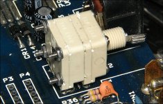
The large white pots can be removed, disassembled, cleaned and reassembled. #2-64 screws can be used to close them back up. You'll have to drill out the holes with a #49 drill bit.
I don't know what you mean by gluing the transformers.
The large white pots can be removed, disassembled, cleaned and reassembled. #2-64 screws can be used to close them back up. You'll have to drill out the holes with a #49 drill bit.
Attachments
- Status
- This old topic is closed. If you want to reopen this topic, contact a moderator using the "Report Post" button.
- Home
- General Interest
- Car Audio
- PPI 2150 died.. :(