I have this hooked up and when testing I notice that only the "Rear Fader" RCA outputs both are equal, but the "Front Fader" & "Main Ouput" RCA's are not the same, the right channel is okay but the left channel is about 1/3 of what the right channel is. For example if the output signal is 2.5v the right is just that but the left channel has 0.85v . I try adjusting the input gain trimmers but I notice those dont function at all. I can move them all the way counterclockwise then clockwise all the way and NO EFFECT to output signal.
There is two opamps (PMI OP275GP) near the input RCA's and below is the readouts for both.
1)2.495 AC
2)2.495 AC
3)2.495 AC
4)-13.11DC
5)0.098AC
6)0.098AC
7)0.098AC
8)13.13DC
1)0.983AC
2)0.983AC
3)0.983AC
4)-13.11DC
5)0.038AC
6)0.038AC
7)0.038AC
8)13.13DC
Dont know if the one with lower readings is damaged, both Left & Right input signals (RCA) are the same so it cannot be my signal source.
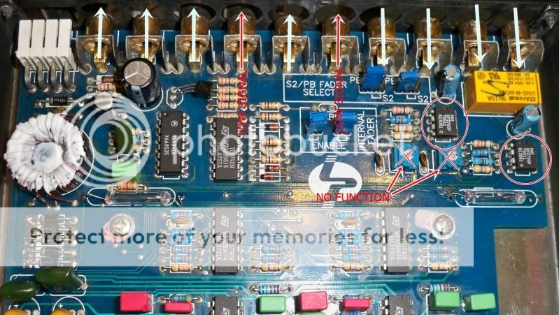
Any help is appreciated. Below is a picture of the actual item in question. The SkyBlue Arrows are input & out signal that are okay.
Red Arrows are the outputs that are very low.
Red "X" are on the trimmer input gains, have no function or effect when rotated.
Red Circle are the opamps, the one the right (close to the edge of the board) is the one that have the low readings.
There is two opamps (PMI OP275GP) near the input RCA's and below is the readouts for both.
1)2.495 AC
2)2.495 AC
3)2.495 AC
4)-13.11DC
5)0.098AC
6)0.098AC
7)0.098AC
8)13.13DC
1)0.983AC
2)0.983AC
3)0.983AC
4)-13.11DC
5)0.038AC
6)0.038AC
7)0.038AC
8)13.13DC
Dont know if the one with lower readings is damaged, both Left & Right input signals (RCA) are the same so it cannot be my signal source.
Any help is appreciated. Below is a picture of the actual item in question. The SkyBlue Arrows are input & out signal that are okay.
Red Arrows are the outputs that are very low.
Red "X" are on the trimmer input gains, have no function or effect when rotated.
Red Circle are the opamps, the one the right (close to the edge of the board) is the one that have the low readings.
An externally hosted image should be here but it was not working when we last tested it.
Last edited:
Not messed with the jumpers. I've gone through the manual a few times and still get confused sometimes, the PA2 had two source inputs and two remote cables so once one source is on thats the one the PA2 will allow through and filter. Which is also the fader/rear input but the jumpers have to be moved from "S2" to ""PB".
The two caps are 4.7uf 50v that are inputs to the RCA's. I checked each with my Fluke 111 for capacitance and both read 4.8uf (thats as far as I can test with my meter,lol).
I can replace them though because I have some in hand.
The two caps are 4.7uf 50v that are inputs to the RCA's. I checked each with my Fluke 111 for capacitance and both read 4.8uf (thats as far as I can test with my meter,lol).
I can replace them though because I have some in hand.
According to the manual, you have the option jumper set incorrectly. The jumpers set for PB (patchback) means that the jumpers for "Internal Fader" need to be removed.
More likely, you want to just remove the "internal fader" jumpers so you can take measurements that will agree with your diagram.
Linear Power - PA2 Manual
More likely, you want to just remove the "internal fader" jumpers so you can take measurements that will agree with your diagram.
Linear Power - PA2 Manual
Last edited:
I know I drew skyblue arrows on the second set of inputs (fader/second source) but I only had one set of channels input, which where connected directly by the yellow relay box.
The other set was unconnected. I dont know if that makes a difference, maybe I have to mess with it some more.
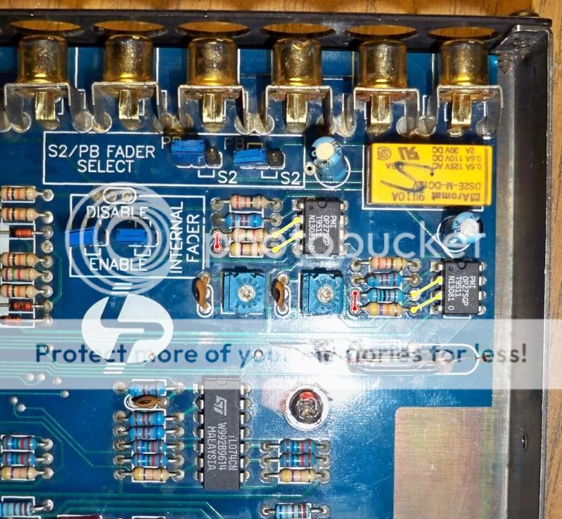
But I do know that the following traces were cut. Dont know if thats making a difference on the trimmers not functioning. Below is a pic, the red traces have been cut, and the yellow traces are good and remain on the board.
The other set was unconnected. I dont know if that makes a difference, maybe I have to mess with it some more.
But I do know that the following traces were cut. Dont know if thats making a difference on the trimmers not functioning. Below is a pic, the red traces have been cut, and the yellow traces are good and remain on the board.
Just checked both trimmer pots (input gain control) and they are good, but are not controlling the input signal. Like I posted before, I rotate them back and foward and no effect to output signal, which is weird because the traces are good, expect for those two red traces I drew on the last pic.

Both are three pins but they only use two of the three pins. I will power it up and check it out. Since the pins are below the board could I check it through the top on the traces?
"Do you read continuity through the two glass devices (no RCAs connected)? "
-By the light bulbs? By continuity you mean would they be "on" if there is no RCA's then yes they do turn on.
Pic on post #6, I replace the traces that were cut (in pic they're RED) and now I have control of the input gain signal and can adjust so both right and left outputs are equal/same.
So problem is fixed and its working perfectly, will see if I can install it pretty soon.
Am still thinking if I should change/upgrade the two opamps (OP275GP), any suggestions? Am thinking OPA2134PA but dont know if there will be problems. Also so I wont be soldering and desoldering I will put IC sockets, I figured it would be a nice and easy mod.
Last edited:
I think you might be splitting hairs by replacing those op-amps
Op275 spec:
Low Noise: 6 nV/ÖHz
Low Distortion: 0.0006%
High Slew Rate: 22 V/ms
Wide Bandwidth: 9 MHz
OP2134PA spec:
ULTRA LOW DISTORTION: 0.00008%
l LOW NOISE: 8nV/ÖHz
SLEW RATE: 20V/ms
BANDWIDTH: 8MHz
In fact the 2134 seems to have less spectacular test results. Since you have those TLO-72 op-amps in circuit directly afterwards it is doubtful any sonic change could be heard over those devices. I have seen the TLO-72's replaced by Burr-Brown devices but it also required that the power supply be beefed up to accommodate the higher current draw they made. As I recall it was one of those hybrid mods from those LP after-market folks back east. There name evades my memory tonight.
IMHO save your money or spend it on something more worthwhile then this device. I have worked on them before myself, and the BB modded one from the after-market company, so my opinion while unsettling to some is based on real world handling of several of these...hope this helps some...")
Op275 spec:
Low Noise: 6 nV/ÖHz
Low Distortion: 0.0006%
High Slew Rate: 22 V/ms
Wide Bandwidth: 9 MHz
OP2134PA spec:
ULTRA LOW DISTORTION: 0.00008%
l LOW NOISE: 8nV/ÖHz
SLEW RATE: 20V/ms
BANDWIDTH: 8MHz
In fact the 2134 seems to have less spectacular test results. Since you have those TLO-72 op-amps in circuit directly afterwards it is doubtful any sonic change could be heard over those devices. I have seen the TLO-72's replaced by Burr-Brown devices but it also required that the power supply be beefed up to accommodate the higher current draw they made. As I recall it was one of those hybrid mods from those LP after-market folks back east. There name evades my memory tonight.
IMHO save your money or spend it on something more worthwhile then this device. I have worked on them before myself, and the BB modded one from the after-market company, so my opinion while unsettling to some is based on real world handling of several of these...hope this helps some...
Okay after doing the traces that were cut, I notice that the left input gain pot had to be almost all the way clockwise while the right input gain had to be all the way counterclockwise just to match the outputs.
Which is not good because now my output signal is low. Then after leaving it on with a sinewave of 2khz the output signal on the "left" op amp was around 6-7v while the right was STEADY at 4v.
So I lower the left input pot almost all the way down to match the right output but the left signal keeps going up and down with different fhz while the right stays steady.
Am thinking the culprit is the left input filter cap which is 4.7uf 50v, no sign of damage but I've dealt with caps that show no damage before.
Okay found the real culprit. I follow the traces for the signal before & after the caps and they where the same (so good, no need to replace caps). Still left signal is 1/3 of right signal even though both signals are from the same source and measure from the input RCA's the same. So I knew some where the signal path was being reduced.
The only place left was the relay switch which allows the PA2 to have two source inputs or front and fader (with the movements of some taps inside). After checking both input and outputs for the relay I notice right away that the "right" side was perfect but the "left" side was being reduce badly and was moving continuously.
So I went ahead and added some power to the second remote cable (for second source) and I heard the relay switch but it must not be making good contact because there was no power on the IC's nor the lights where on. After 30 or so clicks I connected the remote for source 1 and re-checked the outputs of the relay and now they where both the same and now both trimmer pots are the same and signal is equal now.
Am going to go ahead and replace the relay since Mouser is a few minutes away, I'll pick it up tomorrow with some other parts.
- Status
- This old topic is closed. If you want to reopen this topic, contact a moderator using the "Report Post" button.
- Home
- General Interest
- Car Audio
- LinearPower PA2, Right channel louder than Left.