Yeah I got tired of always waiting on parts so I decided to spend alot of money and stock thousands of parts. As many of these as I repair a week it was in my best intrest.
On an average I repair about 20 amps a week mostly Rockford, now that work has slowed down for the winter months I will have more time for repairs.
It has been a profitable hobby. Lets keep in touch on this post I am sure we will have alot of the same issues with our basket cases.
On an average I repair about 20 amps a week mostly Rockford, now that work has slowed down for the winter months I will have more time for repairs.
It has been a profitable hobby. Lets keep in touch on this post I am sure we will have alot of the same issues with our basket cases.
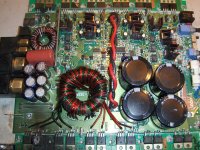
Amp is prepped and ready for new parts.
Here is my list so far.
Protection led light, remote lead, subsonic filter switch, phase switch, rca jacks, 6 power supply capacitors, 8 power supply fets, 8 power supply gate resistors, 2 pnp and 2 npn driver transistors, 6 output fets, 6 output fet gate resistors, 1 MIC4420CT low side mosfet driver, 1 Optocoupler, 1 Op-amp, and we will start with that.
I will get everything replaced and fire up the amp and view the drive circuit and output through the scope.
OK
Replaced 6 power supply caps, 2 pnp and 2 npn drivers for power supply, replaced 8 power supply fets, 8 gate resistors for the power supply fets, remote lead, protection led light, phase switch, subsonic switch, RCA jacks and that is it so far.
I powered up the amp and NOTHING!!! No lights no NOTHING!!!
I cant think of anything I missed, something must be wrong with the turn on circuit??
I am getting voltage at the LM339 just not sure where to look??
What did I miss??
pin 1: 0.562 vdc
pin 2: 0.002 vdc
pin 3: 2.056 vdc
pin 4: 0.288 vdc
pin 5: 13.31 vdc
pin 6: 0.001 vdc
pin 7: 0.215 vdc
pin 8: 13.32 vdc
pin 9: 1.946 vdc
pin10: 1.806 vdc
pin11: 0.162 vdc
pin12: 0.655 vdc
pin13: 1.711 vdc
pin14: 0.110 vdc
pin15: 0.001 vdc
pin16: 0.001 vdc
pin17: 0.043 vdc
pin18: 0.669 vdc
I would have to say defective wouldnt you?
I replaced the U17 and 1/2 of the output fets that were defective. I powered up the amp and all was good. I viewed the drive circuit again through the scope and it looked perfect. I viewed the gate drive circuit on the output fets and it all looked perfect. I also viewed the opto-couplers and a few op-amps and all signals looked perfect.
I tested for sound and the amp produced sound and clean audio on the scope.
I bolted the board down in the heatsink and when power was applied via remote terminal the amp went into direct short, full draw and almost killed my power supply. I dis connected everything and was like WTF?????
I removed the amp from the heat sink and as soon as the power and ground were hooked up (no remote) same thing dead short, full draw on my supply.
I removed all the power supply fets and replaced the 2 pnp and 2 npn drivers (again). I hooked up the power and ground and it seemed fine. I then connected the remote terminal and still no short. While the remote terminal was hooked up I viewed the drive circuit on the scope and all was perfect square waveform.
I didnt have any solder bridges, and to the best of my knowledge upon careful inspection nothing from the amp was touching the heat sink. I powered the amp up many times out of the sink with no issues.
Why would it short the power supply fets upon installation into the heat sink?? The 5 screws that hold the board down are all grounds for various paths in the circuit board.
Could a few of the power supply fets been leaky after tinning them?
If so why did it power up fine out of the sink?
I am at a loss???
I screwed the board down in the sink with the power supply fets removed and applied power ground and remote. The drive circuit still looks perfect.
I only installed the 5 screws that hold the board to the sink, none of the mesha board screws.
Is there a possible way the mesha board could become conductive??
I dont see any discoloration or burn or arc spots on it.
I dont know what to think, however I would like some opinions before I waste my time smoking 8 more power supply fets.
- Status
- This old topic is closed. If you want to reopen this topic, contact a moderator using the "Report Post" button.
- Home
- General Interest
- Car Audio
- Rockford FOsgate BD1000