The power supply fets were shorted in this amp, 75339's. After replacing them the plus rail reads 49.6V and the negative reads -42.3Vdc. The +- voltage on the op-amps is also odd, +18Vdc and -14Vdc, it looks to be derived from 1n4745 16V zeners.
The op-amp voltage could be messed up from the rail voltage being off, but why are the rails so different?
Should I adjust the bias pots full CCW?
The op-amp voltage could be messed up from the rail voltage being off, but why are the rails so different?
Should I adjust the bias pots full CCW?
This is typically caused by defective rectifiers. One broken leg is most common. Confirm that you have the same voltage swing on the input legs of the rectifiers. If the amplitude there is the same for both rectifiers but the output voltage is not, replace the rectifier.
In some of the MTX amps, they use the B+ to produce part of the rail voltage. If that's the case in this amp, the B+ voltage could have an effect on the rail voltage.
For the regs, compare the voltage on the zeners and the voltage on the various points of the regulator circuit to see where the voltage isn't right. Many of the MTX amps use ±18v for the regulated voltage. I'm not sure what this amp has.
The input swing is different between the two, the one with lower output has a higher swing???
With the outputs loaded in a bridged config the rails come to within 2.5Vdc of each other and the +- Reg voltages come closer as well. There must be some difference in the transformer windings?
With the outputs loaded in a bridged config the rails come to within 2.5Vdc of each other and the +- Reg voltages come closer as well. There must be some difference in the transformer windings?
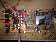
So i have the same amp for a repair. PS, output section a lot of diodes dead, a lot of damage but all the traces are good so i'm going to give it a shot.
I've pulled out all of the PS and Output fets, removed even the rectifiers. This amp has been repaired very badly before me, so i don't really trust that this are the original parts.
Gate drive looks great, so i've decided to put two sacrificial IRFZ44N, one per bank for testing purposes. I get 1.8A of constant current pull from my power supply. Fets get very hot quickly. I've removed them and put a new ones p60nf06 (these were the ones which were fitted when the amp came for a repair but i think the original ones are HUF75339 according to another thread in this forum). Same. Tried with irf3205 - same...so it's not the FETs, its not the TL494, not the buffer transistors, because gate drive looks great.
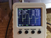
I've checked the center pin of the positive rectifier. Without remote in - 0v. The other two pins are at 12v. When I apply remote, center pin gets 12v slowly rising from 0.
But the wave at the other two pins looks awful (this is without the rectifiers in). I wil attach pictures.
If I fit the rectifiers back - same - 1.8A of current pull and fets get hot quickly. I'm pretty sure 2A of current at idle is way to much for this amp. Maybe it does need all of the 6 FETS in the PS ?!
I've pulled out all of the PS and Output fets, removed even the rectifiers. This amp has been repaired very badly before me, so i don't really trust that this are the original parts.
Gate drive looks great, so i've decided to put two sacrificial IRFZ44N, one per bank for testing purposes. I get 1.8A of constant current pull from my power supply. Fets get very hot quickly. I've removed them and put a new ones p60nf06 (these were the ones which were fitted when the amp came for a repair but i think the original ones are HUF75339 according to another thread in this forum). Same. Tried with irf3205 - same...so it's not the FETs, its not the TL494, not the buffer transistors, because gate drive looks great.
I've checked the center pin of the positive rectifier. Without remote in - 0v. The other two pins are at 12v. When I apply remote, center pin gets 12v slowly rising from 0.
But the wave at the other two pins looks awful (this is without the rectifiers in). I wil attach pictures.
If I fit the rectifiers back - same - 1.8A of current pull and fets get hot quickly. I'm pretty sure 2A of current at idle is way to much for this amp. Maybe it does need all of the 6 FETS in the PS ?!
- Status
- This old topic is closed. If you want to reopen this topic, contact a moderator using the "Report Post" button.
- Home
- General Interest
- Car Audio
- MTX RT2400X Rail voltages different