I just bought a pioneer gm-2000A.
Its in lets say mint condition on the inside.
All pieces made in japan.Tranzistors, etc.
Problem is that I don`t have a remote option.
I hooked it up to the car, it starts, it gets power, but it doesent play.
What can I do to start it?How can I by-pass the rem function or how do I connect it ???
I`m sorry if I posted in the wrong forum thread .
I`m new and this is my first post.
Best regards !
Either tap the power antenna lead on the radio or install a single pole toggle switch between the b+ and the rem terminal on the amp. Just don't forget to turn it off or the amp will kill your battery. Another option if you don't have a rem lead or power antenna lead on your radio is to run the rem lead to the power wire on the radio so the ignition key will turn the amp on and off. This will at least make it so you don't kill your battery by leaving a switch on by accident.
I found service data for the Pioneer GM-2000. It shows a "B3" blue wire remote connection. I wouldn't expect a great difference with a 2000A model. See how well it matches what you have. Though there are a few "it has no remote" help questions that show up in Google for these amps.
What do you mean by "I don`t have a remote option"?
the amp doesen`t have remote.it only has - + .no remote to bridged it to the +.
Either tap the power antenna lead on the radio or install a single pole toggle switch between the b+ and the rem terminal on the amp. Just don't forget to turn it off or the amp will kill your battery. Another option if you don't have a rem lead or power antenna lead on your radio is to run the rem lead to the power wire on the radio so the ignition key will turn the amp on and off. This will at least make it so you don't kill your battery by leaving a switch on by accident.
i don`t have the rem function on the amp (as far as i can tell).I tried it on my car, but got signal for it from my phone (music etc).
the amp powers up, but no music played in speakers.
I found service data for the Pioneer GM-2000. It shows a "B3" blue wire remote connection. I wouldn't expect a great difference with a 2000A model. See how well it matches what you have. Though there are a few "it has no remote" help questions that show up in Google for these amps.
i read a bunch.thats why I made an account here.I could not understand the information I found so I though I should ask myself and figer it out now.
it has 2 leads - + , the speaker leds (4 + - . - + ) anoter 4 pin conector (wich I believe is the speakers again, and a DIN 5 pin signal input and 2 RCA inputs.(I thought it could help).
That's what I was hoping you'd tell us.Do I need to connect that too or is thhis spec only for GM-2000 and not 2000-A
")
If it doesn't already have a remote switch connection, you have extra install work. Therefore it's worthwhile to open it up and compare your board with the layout shown in the docs. If it's similar enough, the questions are more easily answered. Maybe it had a previous mod?
That's what I was hoping you'd tell us.
If it doesn't already have a remote switch connection, you have extra install work. Therefore it's worthwhile to open it up and compare your board with the layout shown in the docs. If it's similar enough, the questions are more easily answered. Maybe it had a previous mod?
its opened.
fac is that it is a standard board.it is been used as default(minor switches) for gm-1000, gm-2000 and another amp.
as I can tell by looking at it and by studying the manual, and other pics on the internet (all amps gm-2000A found on the internet have 2 cables comming out) that would be the right thing to do.
I wanna ask someone befor i do it so that I might not fry it .(Heaven NO
) )I attached a photo.From what i can tell by looking at the board and the manual I repet myself.they kind`a look a like.
p.s.
the board is fliped upside down to be like in the manual.In the manual you see its "Belly".Not the frond as I show it in the picture
Attachments
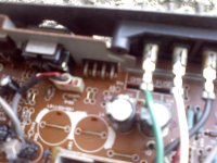
You need to apply 12v to the two center pins of that 4-pin connector. You need to insert a 3-5 amp fuse in the wire between the 12v source and the connector that you use to connect to those two pins in case you accidentally short to the case of the amp when making the connection (I'm assuming that you don't have the original connector).
You need to apply 12v to the two center pins of that 4-pin connector. You need to insert a 3-5 amp fuse in the wire between the 12v source and the connector that you use to connect to those two pins in case you accidentally short to the case of the amp when making the connection (I'm assuming that you don't have the original connector).
no.I don`t have the original connector.
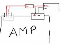
Please corect me if I`m wrong in the picture i just made and attached.
p.s. can I find a "standard" socket fuse so that it may be more easy to connect it?or do I simply connect it to the wire (i don`t know the word but i`m trying to say that i will "glue" it with fludor.(i think)
Attachments
I don't know if this applies here, but early Pioneer amps had a "power out" lead that supplied 12v to the head unit. When the head unit was switched on, the amp sensed the current flow and turned itself on. Presumably, if you powered the amp with unswitched 12V, it would be wise to add a relay between the amp and head unit (relay coil fed from "ignition" or "acc") so as to prevent the radio and amp staying on after the ignition is switched off.
To turn on an amp like that from a modern head unit, maybe use a small (and decorative) 12V lamp as a load, and switch it with a relay (or power transistor). Although it would obviously be better to modify the amp to work with a simple +12V input. Or place the amp in a display case or trade it to someone who REALLY wants a period system in his classic car.
To turn on an amp like that from a modern head unit, maybe use a small (and decorative) 12V lamp as a load, and switch it with a relay (or power transistor). Although it would obviously be better to modify the amp to work with a simple +12V input. Or place the amp in a display case or trade it to someone who REALLY wants a period system in his classic car.
Last edited:
The diagram is correct. You can use the same type of connector that slides onto a speaker terminal. Use one with the same spacing as the pins. You may have to crimp it slightly to make good contact with the pins.
I don't know what fludor is. All you need is crimp connections.
You may want to connect the terminal to the 4-pin connector, then make the connection to the 12v terminal to prevent blowing the fuse (if you short to the case of the amp).
I don't know what fludor is. All you need is crimp connections.
You may want to connect the terminal to the 4-pin connector, then make the connection to the 12v terminal to prevent blowing the fuse (if you short to the case of the amp).
I have made this "strap"...
joined the 2-3 pins and hooked them up to the 3 a fuse (if it blows i`ll switch to 5).
is there a problem with the set up?should I have put them on their own wire???
the wireing is in paralel if i am not mistaken.should I have seried them?
joined the 2-3 pins and hooked them up to the 3 a fuse (if it blows i`ll switch to 5).
is there a problem with the set up?should I have put them on their own wire???
the wireing is in paralel if i am not mistaken.should I have seried them?
Attachments
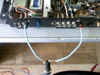
It looks OK.
If the amp powers up and works properly, you'll need to use a switched power source instead of the 12v B+ terminal of the amp. Using the constant B+ terminal will make the amp remain on. The remote output on the head unit should be used as the switched power source. If that's not available, use a power source switched on/off with the ignition switch. See post #3.
If the amp powers up and works properly, you'll need to use a switched power source instead of the 12v B+ terminal of the amp. Using the constant B+ terminal will make the amp remain on. The remote output on the head unit should be used as the switched power source. If that's not available, use a power source switched on/off with the ignition switch. See post #3.
i`ll test it out shortly..let you know how it works.
keep your fingers crossed
fingers crossed and it worked.
Thank you all for posting and for helping me figer it out.
After this short but succesfull experience.....diyaudio nr 1 in my book every day!
Thaks again for posting !
p.s. 1
if I am not mistaken the 2 ohm is in bridged mode no?
i can`t listen to 2 ohms in stereo correct?
4 ohm for stereo , 2 ohm in bridged correct?
p.s.2
lets hope that now who ownes or gets his fingers on an amplifier like this will be able to find/read this post and get it toghether !
Last edited:
- Status
- This old topic is closed. If you want to reopen this topic, contact a moderator using the "Report Post" button.
- Home
- General Interest
- Car Audio
- Please help !!!