Hi everyone, I'm new to the board after researching for some help in repairing a PPI A404. I'm a fan of old school PPI equipment and am getting back into the hobby after a number of years being out of it. 
That being said, I'm not new to repairing amps including the older PPI's, Orions, Rockford Fosgates, etc. I've actually repaired a number of them in the PPI line including A600, 2075AM's, 4200AM's, etc. But this 404A has got me stumped.
For those of you who know more of the inner working of this amplifier, I would appreciate any help into what I need to repair this amp.
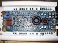
I'm posting the following data for those certain components that may be of assistance to those in helping with the troubleshooting aspects.
PPIA404
Power Supply
M1- M8 Mosfets - SMP25N06 - Gate = 3.56V, Drain = 13.67V, Source = 0V
CR1 + 2 Rectifiers FESF8DT - Cathode = 22.93V, Anode = -0.465V
CR28 + 29 Rectifiers FESF8DT - Cathode = -23.88V, Anode = -0.465V
Q1 BDT81 / NPN Bi-polar transistor used as a regulator --> B = 14.94V, C = 37.6V, E = 14.69V
CR5 Zener Diode 1N4744A - Cathode = 14.95V, Anode = -0.468V
Q77 BDT82 / PNP Bi-polar transistor used as a regulator --> B = -15.80, C = -38.40V, E = -15.24V
CR26 Zener Diode 1N4744A - Cathode = -0.468V, Anode = -15.80V
U1 SG3525A Pulse width modulator
Pin 1 Inverted Input = 2.6V
Pin 2 Non-Inverted Input = 2.598V
Pin 3 Sync = 0.22V
Pin 4 Osc Output = 0.191V
Pin 5 Ct = 2.042V
Pin 6 Rt = 4.31V
Pin 7 Discharge = 2.511V
Pin 8 Soft Start = 4.92
Pin 9 Compensation = 2.309V
Pin 10 Shutdown = 0.002V
Pin 11 Output A = 3.56V = drives the MOSFETS at the Gate
Pin 12 GND = 0.002V
Pin 13 Vcc = 13.21V
Pin 14 Output B = 3.56V = drives the MOSFETS at the Gate
Pin 15 Vcin = 13.21V
Pin 16 Vref = 5.20V
Output Transistors
Q2, Q3, Q6, Q7 - BDT82
B = -1.097V, C = -23.82V, E = -0.570V
Q4, Q5, Q8, Q9 - BDT81
B = 0.025V, C = 22.87V, E = -0.549V
Q78, Q79, Q82, Q83 - BDT81
B = -0.019V, C = 22.87V, E = -0.549V
Q80, Q81, Q84, Q85 - BDT82
B = -1.081V, C = -23.82, E = -0.549V
U2 4N25 Phototransistor Optoisolator
Pin 1 - Anode = 1.070V
Pin 2 - Cathode = 0.02V
Pin 3 - N/C = 0.00V
Pin 4 - Emitter = -15.33V
Pin 5 - Collector = -15.13V
Pin 6 - Base = -14.71V
U5 LM833N Op amp
Pin 1 / Out A = - 5.74V
Pin 2 / - In A = - 1.187V
Pin 3 / + In A = - 0.467V
Pin 4 / - VEE = -15.08V
Pin 5 / + In B = - 0.467V
Pin 6 / - In B = - 1.187V
Pin 7 / Out B = - 5.74V
Pin 8 / + VCC = - 6.44V
After all this data, everything looks pretty good to me. The power light isn't coming on. The center of PCB LED DS1 does not come on either. DS2, DS3 - Red Power on and Amber Low impedance LED's don't come on either. The LED for the power should come on. I've checked the LED's with the diode check on a meter and they are both good as they light up when checked.
I have not hooked any speakers up or any resistor loads to the speaker leads to avoid having the transistors burn up without heatsinking fully installed. I could just put it all back together and chance it on a speaker in the car and see if it works, but I at least would like to have the power LED working before doing that though...
I've also checked the electrolytic capacitors and taken them out and they all come up good. I've used capacitance meters, ESR meters, resistance ohm's to see if any were shorted, and even used a Sencore Auto Z Capacitance Checker.
I've also checked resistors to see if there were any that were open.
I have a scope if there are some waveforms that someone would like for me to check. Also, if anyone who worked for PPI, etc. or somehow has the 404A schematic and especially the voltages for test points and or waveforms for scope use would be extremely appreciative.
That being said, I'm not new to repairing amps including the older PPI's, Orions, Rockford Fosgates, etc. I've actually repaired a number of them in the PPI line including A600, 2075AM's, 4200AM's, etc. But this 404A has got me stumped.
For those of you who know more of the inner working of this amplifier, I would appreciate any help into what I need to repair this amp.
I'm posting the following data for those certain components that may be of assistance to those in helping with the troubleshooting aspects.
PPIA404
Power Supply
M1- M8 Mosfets - SMP25N06 - Gate = 3.56V, Drain = 13.67V, Source = 0V
CR1 + 2 Rectifiers FESF8DT - Cathode = 22.93V, Anode = -0.465V
CR28 + 29 Rectifiers FESF8DT - Cathode = -23.88V, Anode = -0.465V
Q1 BDT81 / NPN Bi-polar transistor used as a regulator --> B = 14.94V, C = 37.6V, E = 14.69V
CR5 Zener Diode 1N4744A - Cathode = 14.95V, Anode = -0.468V
Q77 BDT82 / PNP Bi-polar transistor used as a regulator --> B = -15.80, C = -38.40V, E = -15.24V
CR26 Zener Diode 1N4744A - Cathode = -0.468V, Anode = -15.80V
U1 SG3525A Pulse width modulator
Pin 1 Inverted Input = 2.6V
Pin 2 Non-Inverted Input = 2.598V
Pin 3 Sync = 0.22V
Pin 4 Osc Output = 0.191V
Pin 5 Ct = 2.042V
Pin 6 Rt = 4.31V
Pin 7 Discharge = 2.511V
Pin 8 Soft Start = 4.92
Pin 9 Compensation = 2.309V
Pin 10 Shutdown = 0.002V
Pin 11 Output A = 3.56V = drives the MOSFETS at the Gate
Pin 12 GND = 0.002V
Pin 13 Vcc = 13.21V
Pin 14 Output B = 3.56V = drives the MOSFETS at the Gate
Pin 15 Vcin = 13.21V
Pin 16 Vref = 5.20V
Output Transistors
Q2, Q3, Q6, Q7 - BDT82
B = -1.097V, C = -23.82V, E = -0.570V
Q4, Q5, Q8, Q9 - BDT81
B = 0.025V, C = 22.87V, E = -0.549V
Q78, Q79, Q82, Q83 - BDT81
B = -0.019V, C = 22.87V, E = -0.549V
Q80, Q81, Q84, Q85 - BDT82
B = -1.081V, C = -23.82, E = -0.549V
U2 4N25 Phototransistor Optoisolator
Pin 1 - Anode = 1.070V
Pin 2 - Cathode = 0.02V
Pin 3 - N/C = 0.00V
Pin 4 - Emitter = -15.33V
Pin 5 - Collector = -15.13V
Pin 6 - Base = -14.71V
U5 LM833N Op amp
Pin 1 / Out A = - 5.74V
Pin 2 / - In A = - 1.187V
Pin 3 / + In A = - 0.467V
Pin 4 / - VEE = -15.08V
Pin 5 / + In B = - 0.467V
Pin 6 / - In B = - 1.187V
Pin 7 / Out B = - 5.74V
Pin 8 / + VCC = - 6.44V
After all this data, everything looks pretty good to me. The power light isn't coming on. The center of PCB LED DS1 does not come on either. DS2, DS3 - Red Power on and Amber Low impedance LED's don't come on either. The LED for the power should come on. I've checked the LED's with the diode check on a meter and they are both good as they light up when checked.
I have not hooked any speakers up or any resistor loads to the speaker leads to avoid having the transistors burn up without heatsinking fully installed. I could just put it all back together and chance it on a speaker in the car and see if it works, but I at least would like to have the power LED working before doing that though...
I've also checked the electrolytic capacitors and taken them out and they all come up good. I've used capacitance meters, ESR meters, resistance ohm's to see if any were shorted, and even used a Sencore Auto Z Capacitance Checker.
I've also checked resistors to see if there were any that were open.
I have a scope if there are some waveforms that someone would like for me to check. Also, if anyone who worked for PPI, etc. or somehow has the 404A schematic and especially the voltages for test points and or waveforms for scope use would be extremely appreciative.
Last edited:
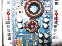
There are two others that have -6.44 on Pin 8. I was trying to find where a 15 volt could possibly come from. I found one transistor by the other DS1 that was about 10.58V. Another one kind of close to it at 13.58V. I'll probably just take a pictire of the amp as that might be easier. Thanks!
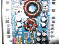
The transistors indicated in the attached image appear to be the voltage regulators. Email me the full resolution images if you need more help.
babin_perry@yahoo.com
babin_perry@yahoo.com
Attachments
- Status
- This old topic is closed. If you want to reopen this topic, contact a moderator using the "Report Post" button.
- Home
- General Interest
- Car Audio
- PPI A404 Amp Dead - Repair Help Needed