Total newb when it comes to trying to repair an amp but this thing has been sitting around for a few years anyway so figured I'd give it a shot.
I checked out the mini tutorial on BCAE and tried to figure out the values of these burnt resistors but I'm not familiar with them enough to know what's red,orange, brown etc. Looks like bands 2,3,4 are Yellow, Black & Gold but the first and last don't seem obvious to me.
There are 4 burnt in total but they all appear to be the same. I've got a close up of one next to what looks like two good ones to get help on what the colors really are. I like to tinker so I'd like to think I have the ability to pull this off with a little bit of guidance. Not sure if something else caused these to fry but figured I'd start with them first and go from there.
An externally hosted image should be here but it was not working when we last tested it.
An externally hosted image should be here but it was not working when we last tested it.
An externally hosted image should be here but it was not working when we last tested it.
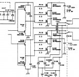
It looks as though R113 same as R116(34ohms), R114 same as R117(34ohms) and R115 same as R118.
resistor color codes:
Graphical Resistance Calculator
resistor color codes:
Graphical Resistance Calculator
if you have a multimeter you can measure the good resistors. From past experience, if u replace the resistors they will just burn again unless u figure out what else is wrong with the amplifier
very true for the smaller resistors but the larger ones like 2 and 3mm ones can get very hot and eventually just fail especially as the solder dries out/evaporates!
but generally, yes there is trouble upstream somewhere

In the Ref 500 schematic resistors R113 through R118 are the 3.3 ohm gate resistors for the power supply FETs. With those resistors being burnt, I'd check the power supply FETs. I'd also check Q107 through Q110 (FET driver trasistors) and make sure they survived.
Attachments
Last edited:
hmmm....I can see the schematic says 3.3ohm but when I try to use a resistor calculator based on the colors I get 34. If I back into getting 3.3 the 4th band would be silver and I certainly don't see any silver bands there. Not sure which side you start from but either way I see it being either yellow or gold/copper.
Is it best to go by the schematic says or what my eyes see?
This seemed like something I thought I should be able to pull off but not sure I'm ready yet. I think I have more reading and learning to do. I'm the type that hates to pay to have something fixed if I think it's something I SHOULD be able to do.
I'd say with those resistors blown the power supply fets are sure to be blown as well. You might want to carefully take the board off of the heat sync and inspect each TO-220 transistors with your ohm meter. Across all three legs en every direction of each transsitor you should not measure any significantly low resistance or shorts (Except across only the rectifiers Legs 1&3).
Took the board off and took a quick look and can certainly see the signs of one burnt up power supply FET. I'll have to check them all but at least this one is obvious to the naked eye.
An externally hosted image should be here but it was not working when we last tested it.
Will do. I assume these are readily available. I'll search through some other topics and find out which ones I'm looking for and where to get them.
The RFP50N05 is no longer made. However, just about any N channel FET rated for 50V/50A and 110W or more will work. You can use the RFP50N06, they are $1.50 at Digikey. Or the IRF3205 would be a very beefy replacement that you would have a hard time blowing up.
In the Ref 500 schematic resistors R113 through R118 are the 3.3 ohm gate resistors for the power supply FETs. With those resistors being burnt, I'd check the power supply FETs. I'd also check Q107 through Q110 (FET driver trasistors) and make sure they survived.
Getting my Reference 500sx worked on and my guy needs the schematic. Is there more to the schematic than what's in your thumbnail?
Getting my Reference 500sx worked on and my guy needs the schematic. Is there more to the schematic than what's in your thumbnail?
Send me a PM with your e-mail address.
- Status
- This old topic is closed. If you want to reopen this topic, contact a moderator using the "Report Post" button.
- Home
- General Interest
- Car Audio
- Need help identifying resistors on Soundstream Reference 500