Hi all,
I have a soundstream rubicon 6.400 that is not working properly. It would make a large popping sound from the speakers and shut down after being on for a couple of seconds. I started trying to troubleshoot but have not got very far. I disconnected the RCA cables and the speaker wires from the amp and it is still going into protection mode. I checked the ground and it appears to be good. None of the three fuses are bad. I want to know if there is anything else I can check on the outside of the amp before having to open it up to look at the guts. Can I find a possible short by checking the speaker outputs or RCAs? Will it go into protection if I don't have a load hooked up to it? Any suggestions would be appreciated, I just want to check as much easy stuff as possible before having to open it up, thanks.
I have a soundstream rubicon 6.400 that is not working properly. It would make a large popping sound from the speakers and shut down after being on for a couple of seconds. I started trying to troubleshoot but have not got very far. I disconnected the RCA cables and the speaker wires from the amp and it is still going into protection mode. I checked the ground and it appears to be good. None of the three fuses are bad. I want to know if there is anything else I can check on the outside of the amp before having to open it up to look at the guts. Can I find a possible short by checking the speaker outputs or RCAs? Will it go into protection if I don't have a load hooked up to it? Any suggestions would be appreciated, I just want to check as much easy stuff as possible before having to open it up, thanks.
I hooked up one set of speakers to a single channel and did not get the popping noise, the set also stayed on for my entire 12 minute drive which it has not done in a longime. I measured DC volts black probe to - red to + across all 4 channels and got .04, -.002, .03, -1.66. Ch1 -4. I will try it with the other set of door speakers and see if they act the same. I have two sets of door speakers tied together with 2ohm resistance I'm pretty sure. I ran the speakers off of channel 2(-.002) when it stayed on and did not go into protection mode. Let me know what else I should check, thanks.
OK, so the channel with the -1.66 has something wrong inside the amp and the other channels are OK, is this correct? I would need to check the transistors or rectifiers inside for that channel? Would it be bad for the amp to just use channels 1 and 2 for my speakers and not hook anything up to 3or 4 or will continuing to use it cause more damage? Thanks for the helpful replies so far.
The channel with 4v is also defective.
I don't know if any damage is being done in the defective channel so I can't tell you that it's OK to use the working channels. It could have a driver or other components heating more than normal (trying to correct for the offset) causing damage to the board.
If you're going to attempt to repair it, you open it up to see if you can see any obvious problems. Before you check anything inside the amp, you need to read the basic amp repair page (link in sig line below). Then you can begin checking the various components.
I've been reading the basic car repair site for a few days now, that's how I found this forum. I figured my problem was inside the amp, I just wanted to make sure that I didn't open it up and create new problems if I didn't have to. If it's already broken I can't make it worse trying to fix it myself, right ") When entering my voltages earlier I was doing it from my phone and did not list it clearly.
When entering my voltages earlier I was doing it from my phone and did not list it clearly.
The readings were
CH1: .04
CH2: -.002
CH3: .03
CH4: -1.66
I was meaning it to say Channels 1-4 were the voltages I entered. I also gave the incorrect model number for my amp, it is a Rubicon 4.600 not 6.400. I hope this clears up my bad info and why I think I have one defective channel.
I opened up the amp today and looked inside, I didn't see anything way out of the ordinary. The fets seem to have heatsinks on them so all I could see was their three legs, not the black part to see if one looks burned up. I'm going to read that section first and try to get those tested tonight. I have a Fluke 179 meter I'm checking with but it doesn't have a diode check, will using ohms work ok? Is there a way of knowing which part of the board is for channel 4 so I can focus on that area? I will try to get a picture of it when the wife gets home with the digital camera. Thanks for the help and hopefully I'll have some more info later tonight.
When entering my voltages earlier I was doing it from my phone and did not list it clearly. The readings were
CH1: .04
CH2: -.002
CH3: .03
CH4: -1.66
I was meaning it to say Channels 1-4 were the voltages I entered. I also gave the incorrect model number for my amp, it is a Rubicon 4.600 not 6.400. I hope this clears up my bad info and why I think I have one defective channel.
I opened up the amp today and looked inside, I didn't see anything way out of the ordinary. The fets seem to have heatsinks on them so all I could see was their three legs, not the black part to see if one looks burned up. I'm going to read that section first and try to get those tested tonight. I have a Fluke 179 meter I'm checking with but it doesn't have a diode check, will using ohms work ok? Is there a way of knowing which part of the board is for channel 4 so I can focus on that area? I will try to get a picture of it when the wife gets home with the digital camera. Thanks for the help and hopefully I'll have some more info later tonight.
There should be circuit board designations that differentiate between the 4 channels.
The meter had diode check. Page 11:
http://www.instrumart.com/assets/108/179-manual.pdf
The meter had diode check. Page 11:
http://www.instrumart.com/assets/108/179-manual.pdf
Ok, so I've been reading through the repair guide and am confused about the transistor testing. I'm attempting to check my power supply and audio transistors. I read that if they are connected in parallel with a bad transistor they can give you faulty readings. Then I read where they have to be removed from the board to test them properly with the diode or ohm test. Do I have to remove these parts from the board to test them properly?
I found some numbers on my transistors that may or may not be helpful.
TIP36C W
TIP35C
I googled these numbers and these appear to be PNP/P Channel transistors meaning they are audio transistors, correct? Would the be more likely than the power supply transistors to fail because I am seeing high voltage on my audio channel?
IRFZ48N
These appear to be my N/power supply transistors.
SF104 CT
SF104 CTA
I think these are superfast rectifiers?
I can pull these and start checking them if that is the proper way to test them now that I know how to use the diode check function on my meter
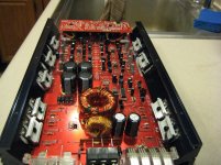
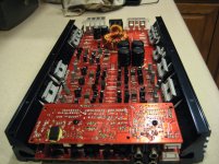
I am attaching two pics of the guts to potentially help with troubleshooting and in case you catch something I didn't. If you would like a closer pic of any area let me know and I can get a more detailed pic. The transistors I listed are grouped along the edge with heatsinks over pairs.
Thanks again for the help.
I found some numbers on my transistors that may or may not be helpful.
TIP36C W
TIP35C
I googled these numbers and these appear to be PNP/P Channel transistors meaning they are audio transistors, correct? Would the be more likely than the power supply transistors to fail because I am seeing high voltage on my audio channel?
IRFZ48N
These appear to be my N/power supply transistors.
SF104 CT
SF104 CTA
I think these are superfast rectifiers?
I can pull these and start checking them if that is the proper way to test them now that I know how to use the diode check function on my meter
I am attaching two pics of the guts to potentially help with troubleshooting and in case you catch something I didn't. If you would like a closer pic of any area let me know and I can get a more detailed pic. The transistors I listed are grouped along the edge with heatsinks over pairs.
Thanks again for the help.
Attachments
Ok, so I've been reading through the repair guide and am confused about the transistor testing. I'm attempting to check my power supply and audio transistors. I read that if they are connected in parallel with a bad transistor they can give you faulty readings. Then I read where they have to be removed from the board to test them properly with the diode or ohm test. Do I have to remove these parts from the board to test them properly?
I found some numbers on my transistors that may or may not be helpful.
**** Start by finding those that appear shorted in the board. If none appear to be shorted (reading something near 0 ohms when the probes are placed across the legs of any individual transistor), you may have to remove them but not initially. Did you find any that were shorted?
TIP36C W
TIP35C
I googled these numbers and these appear to be PNP/P Channel transistors
**** N-channel or P-channel is used for FETs. These are BJTs. The 35 is an NPN transistor. The 36 is a PNP transistor.
meaning they are audio transistors, correct?
**** In this case, they are being used as audio transistors.
Would the be more likely than the power supply transistors to fail because I am seeing high voltage on my audio channel?
**** The problem is likely in the audio circuit than in the power supply circuit and the 35/36 could be the problem but with only 1.6v, the problem is likely elsewhere.
IRFZ48N
These appear to be my N/power supply transistors.
**** These are the power supply transistors. They are N-channel FETs.
SF104 CT
SF104 CTA
I think these are superfast rectifiers?
**** Yes
I can pull these and start checking them if that is the proper way to test them now that I know how to use the diode check function on my meter
I am attaching two pics of the guts to potentially help with troubleshooting and in case you catch something I didn't. If you would like a closer pic of any area let me know and I can get a more detailed pic. The transistors I listed are grouped along the edge with heatsinks over pairs.
Sorry it took my post too soon
IRZF48 (8 total, they all measured about the same)
Leg 1-2 230KOhm
Leg 1-3 300Ohm
Leg 2-3 -200KOhm
TIP36CW (4 Total)
Leg 1-2 300KOhm
Leg 1-3 300KOhm
Leg 2-3 -200KOhm
TIP35C (4 Total)
Leg 1-2 150KOhm
Leg 1-3 300KOhm
Leg 2-3 225KOhm
SF104 CT (2 Total)
Leg 1-2 Between 500KOhm or it would climb to open
Leg 1-3 0.2Ohm
Leg 2-3 500KOhm
Let me know what else I should be checking, thanks
I ended up pulling the board out of the amp base to reach the bottom pins of the transistors because I couldn't reach them from the top. I think I have my defective section narrowed down, there is a green wire going from Channel 4 to 1 of 4 identical squares of pieces. I checked the smaller transistors(anything with 3 legs?) and none were shorting out. A few would read open between points, but they seemed to be doing that all over so I don't think that is a problem. I did not write down all the measurements I took because I'm in a hurry, I have to leave for work in a few, but nothing seemed extremely low or out of whack. I read quite a few in the 200KOhm range. I will try to get a more accurate comparison between the channels next. If those come back ok what should I check next? Resistors, Capacitors? Thanks again for all the help.
- Status
- This old topic is closed. If you want to reopen this topic, contact a moderator using the "Report Post" button.
- Home
- General Interest
- Car Audio
- Troubleshooting Soundstream Rubicon 6.400