I am working on another 500/1 seperate from the one I posted about a few weeks earlier.
I replaced the IRFZ44's and their gate resistors and the IRF540's.
When I powered it up, it cycles on and off. Green LED will also shut off during the cycling. I am using a 5A fuse and 3 Ohm resistor in line with the B+. I know sometimes these amps are sensitive to having the resistor in line, so I removed it and it pops the 5A fuse right away. I checked for solder bridges and there are none. While checking resistances on the outputs, I find that the two inner pair of 540's seemed a little low compared to another amp (K Ohms instead of M Ohms) so I back tracked to U500 which looks like it has over heated and two resistors that don't measure right. R669 should be 10 Ohms but measures inconsistantly ~50K and the resistor next to it should be 100 Ohms and measures ~2.5K.
If I replace those parts, are they the only ones that are suspect considering the symptoms, or are there more areas I need to check?
Attachments
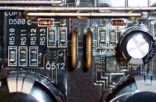
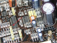
Remove the outputs and short the pins indicated in the attached photo. That should give you a clean square wave on the input to the MIC4427. Yo can then check the output signals.
If you have to replace it, removing the two adjacent capacitors makes it much easier.
If you have to replace it, removing the two adjacent capacitors makes it much easier.
Attachments
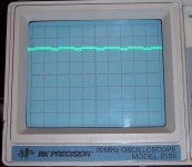
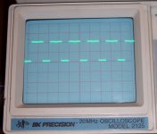
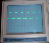
With the scope set to 5V div and 5mS div, I get two solid traces at 0 and +5VDC on both inputs and one solid trace at +5VDC on the outputs of the 4427.
The amp continues to cycle on and off, but after several cycles it quits and apears to remain on. I haven't measured the current draw at this point, but the power supply's analog panel meter indicates ~2A. The inline resistor is hot to touch.
The amp continues to cycle on and off, but after several cycles it quits and apears to remain on. I haven't measured the current draw at this point, but the power supply's analog panel meter indicates ~2A. The inline resistor is hot to touch.
It appears to be defective , assuming that you have supply voltage on the IC.
Use this to continue troubleshooting until you get a clean signal all of the way to the outputs. For the high-side FETs, you'll have to connect the source legs to ground to see the square wave. This is ONLY to be done with no outputs in the circuit.
Use this to continue troubleshooting until you get a clean signal all of the way to the outputs. For the high-side FETs, you'll have to connect the source legs to ground to see the square wave. This is ONLY to be done with no outputs in the circuit.
I do have +15V on Pin6 of the 4427.
So, replace the 4427 and the two resistors for sure.
When I look up the data sheet for this MIC4427BM I see it shows a delay time of 40ns. There are several varieties of this chip with different delay timings, does it matter with how it used here?
I have to order the 4427, are there other things that I need to verify now so I can put in one order?
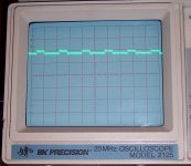
I received the new 4427 today, installed it, repaired the two burned resistors and now have good signal all the way to the output gates. However, the new driver IC didn't cause the amp to stop cycling on & off.
I removed the jumper on pins 1 & 2 and reinstalled the outputs anyway.
If I remove my 3 Ohm resistor from B+ the amp will stay on, however it draws ~10A which slowly blows the 5A fuse. It blew slow enough to see that I did have ~39V between the output terminals and GND.
I briefly replaced the 5A fuse with a 9A fuse and watched the current rise to above 10 amps and shut it down right away so it probably will draw a lot more if allowed.
What should I check on next?
I had my digital meter inline to measure current draw, but it didn't provide consistant usable data for post #17. Removing it to measure the DC on the outputs caused the amp to draw more current which peaked ~20A on the panel meter. I promptly shut it down preserving the fuse. Meter displayed -395.5mVDC as it's peak hold. A sign of output driver damage?
- Status
- This old topic is closed. If you want to reopen this topic, contact a moderator using the "Report Post" button.
- Home
- General Interest
- Car Audio
- JL Audio 500/1 v1 Rev. 10 Boards #2