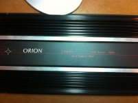
I have a Gen. 1 Orion 2350GX that is having issues. If anyone has any info or pointers for this model it is greatly appreciated.
I'll start with the symtoms. Left channel seems to work fine. Right channel seems to make some sound but no power at all. What I mean by that is, I could hear some very faint sound but not enough to move my 15" L7 at all. I opened up the amp to perform a visual inspection and right away I could see a burnt diode in the middle of the board. So I thought cool, that I can fix. After replacing it with the same part, I put it back together and rushed it back out to the car to hook it up, and to my total suprise it didn't work!
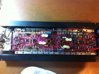
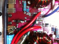
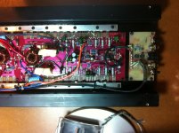
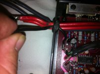
Now I've read the complete section on basic amp repair for a full hour and I think I'm ready to attemp my first amp repair. I am pretty much learning as I go, so you may have to explain things to me as if I were a small child(I won't be offended). Below are a few pictures of my sick baby. The close up picture of diode is the one I replaced. Solder looks nasty but I had to cover over a burnt trace on the board. Hopefully tonight I will get a 12v power supply wired up with a 5 or 10amp fuse inline to start taking some measurements according to the info on Perry's amp repair page.
I'll start with the symtoms. Left channel seems to work fine. Right channel seems to make some sound but no power at all. What I mean by that is, I could hear some very faint sound but not enough to move my 15" L7 at all. I opened up the amp to perform a visual inspection and right away I could see a burnt diode in the middle of the board. So I thought cool, that I can fix. After replacing it with the same part, I put it back together and rushed it back out to the car to hook it up, and to my total suprise it didn't work!
Now I've read the complete section on basic amp repair for a full hour and I think I'm ready to attemp my first amp repair. I am pretty much learning as I go, so you may have to explain things to me as if I were a small child(I won't be offended). Below are a few pictures of my sick baby. The close up picture of diode is the one I replaced. Solder looks nasty but I had to cover over a burnt trace on the board. Hopefully tonight I will get a 12v power supply wired up with a 5 or 10amp fuse inline to start taking some measurements according to the info on Perry's amp repair page.
I know this amp and have repaired several of them back in the day and they are just not that strong of a amp.
This amp is actually TWO orion 275's and the white board up front is the bridging module so the 4 channels are only two on the output and since they are internally bridged together to form a single channels the two outputs this amp has CANNOT be bridged together...
As far as the amp being silent, well how big of a power supply are you using to start the amp up with ?? As I recall the inrush current demand of this amp was around 7 to 10 amps just to fire the amp up. mostly due to the power supply design. by this I mean if you don't have at least a 10 to 20 amp supply the amp will fault and not turn on.
Other then that, the gain pot up front is pretty much a ten turn wonder that rarely escaped needing to be replaced, and is known for having open areas of no contact inside the pot body. Bad gain pot = no sound
Also how did you wire up the L7 ? This amp is bridged inside on each output so unless you run each output to its own voice coil, you will never get the full power the amp has and then you have to be vary careful about connection polarity's as you can null the output by mixing up the phases on a dual coil setup.
Perry has a very valid question about both amps being powered at the same time as one of the amps supplies the bridge board up front with +&- 15 volts DC to operate with. So BOTH amps must be powered and that means all power wires connected and to a supply at least 15 to 20 amps to get this thing started properly due to inrush current demand of the BJT power supplies. It will idle around 2.25 amps if all is normal, but first power up inrush is huge usually pegging a 10 amp current meter I used on my very older power supplies.
The amp looks fine, and to be very pristine condition for its age by the way") .
.
This amp is actually TWO orion 275's and the white board up front is the bridging module so the 4 channels are only two on the output and since they are internally bridged together to form a single channels the two outputs this amp has CANNOT be bridged together...
As far as the amp being silent, well how big of a power supply are you using to start the amp up with ?? As I recall the inrush current demand of this amp was around 7 to 10 amps just to fire the amp up. mostly due to the power supply design. by this I mean if you don't have at least a 10 to 20 amp supply the amp will fault and not turn on.
Other then that, the gain pot up front is pretty much a ten turn wonder that rarely escaped needing to be replaced, and is known for having open areas of no contact inside the pot body. Bad gain pot = no sound
Also how did you wire up the L7 ? This amp is bridged inside on each output so unless you run each output to its own voice coil, you will never get the full power the amp has and then you have to be vary careful about connection polarity's as you can null the output by mixing up the phases on a dual coil setup.
Perry has a very valid question about both amps being powered at the same time as one of the amps supplies the bridge board up front with +&- 15 volts DC to operate with. So BOTH amps must be powered and that means all power wires connected and to a supply at least 15 to 20 amps to get this thing started properly due to inrush current demand of the BJT power supplies. It will idle around 2.25 amps if all is normal, but first power up inrush is huge usually pegging a 10 amp current meter I used on my very older power supplies.
The amp looks fine, and to be very pristine condition for its age by the way
.
Last edited:
The setup I used was: 2-15"L7's single 4ohm voice coil, in a sealed box and signal is from a AudioControl EQX. Unfortunaltly the EQX is getting its signal from line level converter that I had to use to tap into the stock deck in my 2003 Taurus(I know this is not ideal for signal imput)and I've checked it and I am getting output on R/L channels, so I know the siginal is getting to the amp. The setup for powering the amp is- Stock charging system, 4ga power wire from battery to 140amp breaker, then on to distrubtion blocks, then 2-1 farad caps. to my horror I just realized that the caps go strait to my amp! WTF. No Fuse inline! Wow! This was wired up by one of the so called "premier shops" in town. This is possibly the source of my problem if not, its gonna get done right before anything else is hooked up. I just removed all the wire loom covering to find more issues with the install. they took the large + power wire from the cap and tied it to the two + power wires via a large butt connector with shrink tubbing over it. This was a stupid way for them to wire up my 12v power wire, from what I know you always use a dist. block when you go from a larger wire to a smaller gauge otherwise you create a pinch point that creates a loss/heat.(Am I missinformed or did they do it wrong?). Anyway the connection is totally melted where they butt connected the 1 powerwire from the cap into the 2 power wires for the amp. I'm rewiring it today with a single power wire to each of the amps 12v imputs and each will have its own fuse inline.(NO butt connetions). This amp did run on this setup for at least 5yrs without issue so I doubt if I have any chance of a warranty for the install but I gonna check anyway.
As far as testing the amp do I need to use a bigger fuse due to the spike on power up? and I know this is probably a dumb question but why are the stock power wires on this amp 14ga if this is supposed to make 350w a side? should I be upgrading those at this time? and please remember you are talking to a young child when it comes to the inside of a amplifier. I know what a FET,CAP,Diode and a Coil looks like but other than that I'm pretty much lost, I'm learning on the job. When you ask about the "Rail" I see two long aluminum rails holding down the FETS but I don't think thats what your refering to. I see on the exsample on the "Basic amp repair" page that one leg of some of the fets are conneted to the + rail via a emmiter resistor, one goes to the speaker, and the third goes to a base resister that is connected to the driver transisters. And some of the FETS are hooked up the same way but are they are conneted to the - rail. When looking at the amp its obvious that there are to amps kinda graphed together in one housing/case. Looking at picture 3 with the imputs on the left side, how do I tell which Fets are + and which are on the -neg side. sorry in advance if my lack of knowledge is frustrating.
As far as testing the amp do I need to use a bigger fuse due to the spike on power up? and I know this is probably a dumb question but why are the stock power wires on this amp 14ga if this is supposed to make 350w a side? should I be upgrading those at this time? and please remember you are talking to a young child when it comes to the inside of a amplifier. I know what a FET,CAP,Diode and a Coil looks like but other than that I'm pretty much lost, I'm learning on the job. When you ask about the "Rail" I see two long aluminum rails holding down the FETS but I don't think thats what your refering to. I see on the exsample on the "Basic amp repair" page that one leg of some of the fets are conneted to the + rail via a emmiter resistor, one goes to the speaker, and the third goes to a base resister that is connected to the driver transisters. And some of the FETS are hooked up the same way but are they are conneted to the - rail. When looking at the amp its obvious that there are to amps kinda graphed together in one housing/case. Looking at picture 3 with the imputs on the left side, how do I tell which Fets are + and which are on the -neg side. sorry in advance if my lack of knowledge is frustrating.
Well each amp should have its own fuse inline on each red wire. I suggest a nice fuse block setup.
The reason why a amp like this can have such small wires on it is because of the ohms law rule that allows for small conductors for very short distances. In your case less then 18 inches I am guessing. The small conductor provides very little voltage drop issues.
Please remember that this amp design is very old, and from a time when this business was in its infancy. So there will be some things like your power connections that do not make sense when compared to more modern current thinking.
As for their install methods, well I have seen worse, but here again I have also seen better, and I do agree that you should clean up any melted connections as they pose a severe voltage drop issue possibility.
Have you checked the speaker itself to see if it works properly with another amp source? I have seen torn wires on voice coils enough, and blown open voice coils also. Please check the speakers with a ohm meter to see if its still around its typical ohm rating. Two 4 ohm loads to this amp should work OK, so your original setup was about the best it could be for what you have.
If all of the above yields nothing then please power up your amp with no speakers or RCAs connected preferably on a test bench with a good regulated power supply and take a voltmeter and tell me what voltage readings you get on the speaker wires for each channel. This is the DC offset value of each amp which tells me a bunch about your amp as to its health and operating status. Perry suggests that you use a head lamp inline to protect the amp from excessive current draw. I agree this works, and will suffice if a good DC power supply with current limiting is not available.
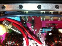
Perry's tutorial is excellent and should have you primed to read transistors and rail supplies inside your amps. It's all simple voltmeter work, but very important to your solution. This amp as I recall has NO MOSFETS in it. They are all Bi-Polar Junction Transistors BJT's. They will be 2N6488 and 2N6491 or there lessor 2N6487 and 2N6490 for the audio outputs. The power supply used either 2N6488 or GE transistors D44VH11 as I recall. The GE device was hard to find even back then and often you would see the the replacement was a 2N6488 as its about the same rated device and will work properly in the power supply.
Your blown diode was what appears to be a simple reverse polarity diode on the plus 12 volt trace to ground. So when someone hooked the amp up backwards to power this diode would short and if the amp was fused properly during setup it would blow the fuse. In your case I am thinking the wiring on the power did no have separate fuses for each red wire so most likely when the amp saw RP on the power it blew the diode open and in this case off the board.
This is not good as it also means that the power supply has seen Reverse Polarity to it and most likely has other damaged components in it due to the power being connected backwards. The only other time I have seen this situation was when all the power supply transistors shorted out and took the positive 12 volt rail to ground. So where you replaced the diode is highly suspect of having bad devices at this point.
And that amp section is also the one that supplies +&- 15 volts to the front end bridging module board, so if that power supply is damaged your input board will not be powered up, and you will have no sound.
The last part above is my best guess with the pics you posted. You will need to test the amp out of the car on a bench for most of the above troubleshooting. there is a fair amount of speculation above but its based only on what I see and what you have told me about the power connections and the history of the system.
Oh and yes please fuse each cap back into the system I have been told a 7 amp fuse to each is acceptable in most cases. Shame is that folks don't know that caps can explode and this is why a fuse is suggested. These types of caps typically have vent plugs on them but you don't want them to vent inside your car, as they spray out the electrolyte in a stream as it boils and ruptures the soft plastic rupture disk on its top. A real nasty smell will linger in your car if this happens.
This is turning into the Magna Charter so get back to me with some of your findings from above....
The reason why a amp like this can have such small wires on it is because of the ohms law rule that allows for small conductors for very short distances. In your case less then 18 inches I am guessing. The small conductor provides very little voltage drop issues.
Please remember that this amp design is very old, and from a time when this business was in its infancy. So there will be some things like your power connections that do not make sense when compared to more modern current thinking.
As for their install methods, well I have seen worse, but here again I have also seen better, and I do agree that you should clean up any melted connections as they pose a severe voltage drop issue possibility.
Have you checked the speaker itself to see if it works properly with another amp source? I have seen torn wires on voice coils enough, and blown open voice coils also. Please check the speakers with a ohm meter to see if its still around its typical ohm rating. Two 4 ohm loads to this amp should work OK, so your original setup was about the best it could be for what you have.
If all of the above yields nothing then please power up your amp with no speakers or RCAs connected preferably on a test bench with a good regulated power supply and take a voltmeter and tell me what voltage readings you get on the speaker wires for each channel. This is the DC offset value of each amp which tells me a bunch about your amp as to its health and operating status. Perry suggests that you use a head lamp inline to protect the amp from excessive current draw. I agree this works, and will suffice if a good DC power supply with current limiting is not available.
Perry's tutorial is excellent and should have you primed to read transistors and rail supplies inside your amps. It's all simple voltmeter work, but very important to your solution. This amp as I recall has NO MOSFETS in it. They are all Bi-Polar Junction Transistors BJT's. They will be 2N6488 and 2N6491 or there lessor 2N6487 and 2N6490 for the audio outputs. The power supply used either 2N6488 or GE transistors D44VH11 as I recall. The GE device was hard to find even back then and often you would see the the replacement was a 2N6488 as its about the same rated device and will work properly in the power supply.
Your blown diode was what appears to be a simple reverse polarity diode on the plus 12 volt trace to ground. So when someone hooked the amp up backwards to power this diode would short and if the amp was fused properly during setup it would blow the fuse. In your case I am thinking the wiring on the power did no have separate fuses for each red wire so most likely when the amp saw RP on the power it blew the diode open and in this case off the board.
This is not good as it also means that the power supply has seen Reverse Polarity to it and most likely has other damaged components in it due to the power being connected backwards. The only other time I have seen this situation was when all the power supply transistors shorted out and took the positive 12 volt rail to ground. So where you replaced the diode is highly suspect of having bad devices at this point.
And that amp section is also the one that supplies +&- 15 volts to the front end bridging module board, so if that power supply is damaged your input board will not be powered up, and you will have no sound.
The last part above is my best guess with the pics you posted. You will need to test the amp out of the car on a bench for most of the above troubleshooting. there is a fair amount of speculation above but its based only on what I see and what you have told me about the power connections and the history of the system.
Oh and yes please fuse each cap back into the system I have been told a 7 amp fuse to each is acceptable in most cases. Shame is that folks don't know that caps can explode and this is why a fuse is suggested. These types of caps typically have vent plugs on them but you don't want them to vent inside your car, as they spray out the electrolyte in a stream as it boils and ruptures the soft plastic rupture disk on its top. A real nasty smell will linger in your car if this happens.
This is turning into the Magna Charter so get back to me with some of your findings from above....
RE: Perry Babin
Thank you for answering my post.
Yes, both 12v+ wires were connected but not properly.(no fuses, just a 140amp breaker) and they were butt connected together to the large power wire off of the caps. I'm aware that this is not how it should have been done and I am fixing it today. Shows that not all "Professional Installers" are made equal(I guess "Professional" just means you get paid to do it. Does not make someone an expert)
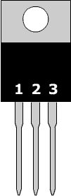
As far as the voltage on leg 3 of the output transistors? Is this where I look up the datasheet for the part# on the output transistor to determine which leg is #3 or are they numbered somewhere? Is it ok to power up (test) the amp with the case/heat sink removed since there is no load/speaker connected? I read somewhere on your page that they must be connected to the heat sink otherwise they will overheat/burn up. Also if it is bad to power up the amp w/o the heat sink connected to the output transistors/FETs how do I check the ones on the bottom of the board. I noticed about a dozen on the bottom of the board when I had it apart to replace the burnt diode. Are they part of the power supply section? Also I have a 10amp 12vdc regulated power supply w/5-10a fuse inline to use for bench testing will this work or should I just grab my car battery w/5-10a fuse inline for testing purposes without a load? Please remember this is all new to me so answer as if you are talking to a semi-dangerous idiot, because Ignorance can be dangerous when playing with wires. As soon as I find out if this is ok to use or not use this little power supply I will have more info. Thanks again
Thank you for answering my post.
Yes, both 12v+ wires were connected but not properly.(no fuses, just a 140amp breaker) and they were butt connected together to the large power wire off of the caps. I'm aware that this is not how it should have been done and I am fixing it today. Shows that not all "Professional Installers" are made equal(I guess "Professional" just means you get paid to do it. Does not make someone an expert)
As far as the voltage on leg 3 of the output transistors? Is this where I look up the datasheet for the part# on the output transistor to determine which leg is #3 or are they numbered somewhere? Is it ok to power up (test) the amp with the case/heat sink removed since there is no load/speaker connected? I read somewhere on your page that they must be connected to the heat sink otherwise they will overheat/burn up. Also if it is bad to power up the amp w/o the heat sink connected to the output transistors/FETs how do I check the ones on the bottom of the board. I noticed about a dozen on the bottom of the board when I had it apart to replace the burnt diode. Are they part of the power supply section? Also I have a 10amp 12vdc regulated power supply w/5-10a fuse inline to use for bench testing will this work or should I just grab my car battery w/5-10a fuse inline for testing purposes without a load? Please remember this is all new to me so answer as if you are talking to a semi-dangerous idiot, because Ignorance can be dangerous when playing with wires. As soon as I find out if this is ok to use or not use this little power supply I will have more info. Thanks again
Last edited:
The transistors should be clamped.
Take and post a photo of the components on the bottom of the board before clamping it back down.
Transistor pin numbering. Looking up the datasheet would have also provided the pin numbering.
The 10 amp supply should be good enough.
If you leave a blank line after each question it makes it much easier to read.
Attachments
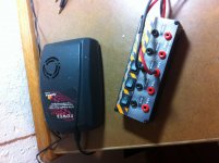
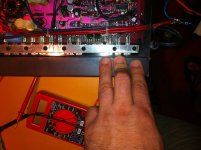
I tried to power up the amp with my little piece of "S" power supply running through a little 10a fused powerstrip (Pic#1). I connected the 2 + power wires together and the 2 - ground wires together. And there is also a 3rd small ground wire or at least thats what it was hooked up to in the car (Pic#2). I don't think this setup is sufficiant to power up this amp. As soon as power was applied the power light on the amp lit up put I could here a "cycling" type whine type sound comming from amp guts. I dissconnected it right away, not wanting to cause any further dammage. It did not blow the 10a fuse but it was almost shutting down the power supply by the sound of it, the little LED on the fused dist. block was flickering pretty bad. Tomorrow I will get a headlight to use with my car battery and try again. Thanks again guys for all your help!
Attachments
I think these amps have a problem with heating the power supply transistors when any resistance is in the B+ line. If you use the headlamp, you MUST clamp the transistors tightly to the heatsink.
Have you checked all of the heatsink mounted transistors to see if any were shorted?
Have you tried connecting only one red wire at a time?
Have you checked all of the heatsink mounted transistors to see if any were shorted?
Have you tried connecting only one red wire at a time?
I tried to power up the amp with my little piece of "S" power supply running through a little 10a fused powerstrip (Pic#1). I connected the 2 + power wires together and the 2 - ground wires together. And there is also a 3rd small ground wire or at least thats what it was hooked up to in the car (Pic#2). I don't think this setup is sufficiant to power up this amp. As soon as power was applied the power light on the amp lit up put I could here a "cycling" type whine type sound comming from amp guts. I dissconnected it right away, not wanting to cause any further dammage. It did not blow the 10a fuse but it was almost shutting down the power supply by the sound of it, the little LED on the fused dist. block was flickering pretty bad. Tomorrow I will get a headlight to use with my car battery and try again. Thanks again guys for all your help!
The extra ground wire was to ground back to your deck to cancel engine noise. At least that was what i was told when I asked 20+ years ago.
The power supply whining sound is caused by the amps not getting enough in rush current to start the amp up. The voltage is dipping below the trip point for the supply to operate properly so it just cycles on and whines like a crying cat. You could try one of your 1 farad caps on the 12 volt supply and see it stores enough to get the amps to fire up properly. Once they have gotten over their initial in rush current issues the amps should turn on fine.
Perry is correct for telling you to try only one channel at a time, as the combined start up current may be dipping your supply down, and one channel might squeak by.
If I were you i would set my voltmeter on current range and then place it in circuit in the negative ground circuit from the 12 volt supply to the amp ground. this would at least tell you what the current is doing. Either that or place your voltmeter on your 12 volt supply as a voltmeter and watch it for dips as you turn on the amps. The 12 volts will drop back low if you don't have enough current to start the amps up, and your meter should catch this.
By the way this is exactly what I was talking about in my earlier posts. this amp and several other old school Orions were all known for this along with a few BJT PPI amps also. It's all about the old transistor based switching supplies they built back then. No such thing as soft start back then I guess. Nothing like the PWM IC based MOSFET design power supplies that came along just after these.
Oh and keep the transistors tightly clamped like Perry said. He knows what I know that these amps had hot power supplies as the power transistors in the power supply just don't switch as effectively as MOSFET's do, so they can and do heat up. The next gen of these amps had MOSFET's and their heat sinks were much smaller as the amp ran cooler.
Last edited:
Sorry for taking so long to get back to you guys. The amp powers up fine w/o issues. The amp draw on the power when Idling is around 4amps.
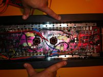
When checking voltage on leg 3 of the transistors I got +16.0v on some and -16v on others and nothing on about 1/2 of them. There were 6 transistors on each end of the board that were separated from the rest (3 on each side of each end, for a total of 12). These had +16v on all of them (both sides, both ends) maybe that’s normal or maybe I can't read a meter??
Working from the ends towards the center (not counting the 3 on each side of each end that are separated from the rest ) there are 17 transistors on each side. It appears that all of the transistors that have no reading are in the middle of the amp on both sides near the coil/transformers. Pic#3 The transistors (first 4-5 from each of the ends have the 16v)
Also I did not get any reading on the speaker wires on either side (Left or right channel) Again I may have done that wrong with the meter. I tried it with the meter set to AC voltage (nothin) so I tried it on DC voltage and again nothing.
I am not very good at explaining this and I am even worse at understanding what I’m doing. It may be best to just have someone repair this. I'm worried I’ll do more damage than good trying to do this myself. I hope this info will help diagnose the issue or estimate a repair cost so I don't get taken advantage of, If I have to have it fixed locally. I might just be disappointed at the moment because I just to understand these things.
Attachments
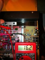
The transistors with the lg. resistor attatched to the third leg are the ones that have beetween +16vdc and 16.2vdc on them (Pict.#1). Is this a good or bad sign?_ Also the amp seems to idle with a 4amp draw on the batt./headlight setup w/15amp fuse inline on the +12v battery cables, I hope this helps. Matt
Attachments
Last edited:
These amps tend to draw more current with the limiter at idle than they do when powered directly (for amps in good working order). 4A is a bit high but doesn't definitively indicate that there is a problem.
16v of rail voltage is low but could be due to being operated through the limiter.
If those have 16v on their 3rd leg, the next 3 to the left should have -16v on their 3rd leg. Confirm.
16v of rail voltage is low but could be due to being operated through the limiter.
If those have 16v on their 3rd leg, the next 3 to the left should have -16v on their 3rd leg. Confirm.
I checked a half/blown (one half not working or drawing current) 2350 that I have here and it pulls ~4 amps with a 2 ohm current limiting resistor in series with the B+ line and about 1 amp when powered directly.
With the 2 ohm resistor in series, the amp produces a rail voltage of ±21v. When powered directly, it produces ±28v of rail.
The information above is simply for reference.
Do you have the same thing (±16v) for both halves of the amplifier?
With the 2 ohm resistor in series, the amp produces a rail voltage of ±21v. When powered directly, it produces ±28v of rail.
The information above is simply for reference.
Do you have the same thing (±16v) for both halves of the amplifier?
- Status
- This old topic is closed. If you want to reopen this topic, contact a moderator using the "Report Post" button.
- Home
- General Interest
- Car Audio
- Old School Orion 2350GX Anyone have tech info?