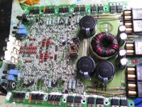
This amp came in with two burn ch.All output transistors and some emmiter resistor was bad in these two ch.I unsolder all outputs and emmiters on these two ch.This amp still will not power up,i think it is going into protect.I pull the center legs of the rectifers off the board and got 41 volts on them but the power light is still off.If the drivers on the two burn ch are bad will it cause that?Any idea what is causing this amp not to power up?
Attachments
Most Rockford amps drive the power LED from the regulated 15v supply. The 15v supply typically gets its power from the rectifiers. If the rectifiers are out of the circuit, the LED can't light up.
When you say it won't power up, does it drag the voltage from the power supply down or does it simply refuse to produce any rail voltage?
When you say it won't power up, does it drag the voltage from the power supply down or does it simply refuse to produce any rail voltage?
I resolder the middle leg of the rectifiers back on the board and now the amp stays power on.I think somthing is about to fail.It has both +&- rail voltage.
LM339
Pin 1: 2.l
Pin 2: 4.7
Pin 3: 13.1
Pin 4: 0
Pin 5: 2.4
Pin 6: 4.8
Pin 7: 4.7
Pin 8: 3.2
Pin 9: 4.8
Pin 10: 4.8
Pin 11: 5.1 plusin to 6.8
Pin 12: 0
Pin 13: 4.3
Pin 14: 4.3
LM339
Pin 1: 2.l
Pin 2: 4.7
Pin 3: 13.1
Pin 4: 0
Pin 5: 2.4
Pin 6: 4.8
Pin 7: 4.7
Pin 8: 3.2
Pin 9: 4.8
Pin 10: 4.8
Pin 11: 5.1 plusin to 6.8
Pin 12: 0
Pin 13: 4.3
Pin 14: 4.3
with the remote connected to 12v direct amp powers up and seem to idle good for about 5 seconds and then it start drawing a little more amps for about 40 seconds and then goes back to how it was idleing when it was just power up . pin1 is plusing and pin6 is 4.6v pin7 is 4.8v
with all ports fully counter clockwise,remote directly connected to 12v amp powers up and stays on.These voltages was taken with black prob on amp main ground.
#339
Pin 1: 13.79
Pin 2: 5.10
Pin 3: 13.15
Pin 4: .17
Pin 5: 2.50
Pin 6: 4.88
Pin 7: 5.49
Pin 8: 3.52
Pin 9: 4.88
Pin 10: 4.88
Pin 11: 6.61
Pin 12: .00
Pin 13: 5.20
Pin 14: 5.20
TL494
Pin 1: 1.99
Pin 2: 2.34
Pin 3: .06
Pin 4: .09
Pin 5: 1.49
Pin 6: 3.34
Pin 7: .00
Pin 8: 13.17
Pin 9: 5.14
Pin 10: 5.14
Pin 11: 3.15
Pin 12: 3.15
Pin 13: 4.88
Pin 14: 4.88
pin 15: 4.88
pin 16: .00
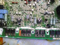
I install the outputs and emitter resistor,now all ch is playing audio.When i turn up the gain audio cuts in and out on all ch.All the bias ports are still counter clock wise.The B+ is connected to a limmiter and the remote is directly connected to 12v.Some times i have to discharge the main caps for the amp to power up.Should i solder the transistors back to the metal strip now?
- Status
- This old topic is closed. If you want to reopen this topic, contact a moderator using the "Report Post" button.
- Home
- General Interest
- Car Audio
- punch 600a4