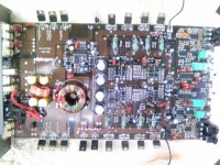
This amp came in with 3 burnt power supply fet and one driver transistor Q20.I replace them , amp powers up and plays audio fine on 3 of the channels.The right front ch plays audio fine when the gain is all the way down.when i turn it up a little it goes in protect.Amp has both + and - rail voltage.The voltage across the emmiter resistors is 0.07mv,the other ch have 0.05mv across the emmiter resistors.This test was done with the gain all the way down while the amp was idleing.Oh and it only goes into protect if a speaker is connected.Any idea where i should start looking for what is causeing that?
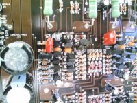
i take it q20 was an output driver by the 2nd pic? can't read it. if so, i would suspect one of the outputs had a changed value or short to over-draw that driver, and is still doing the same thing. have you measured the resistance between the legs compared to the other channels? also, i would look at the caps/resistors by the output terminal. my .02
Are the emitter resistors within tolerance?
Can you determine which transistor is being used for over-current protection. It's likely to be an NPN transistor with one leg directly connected to one of the emitter resistors and a diode connected to its collector. Find it and remove it. Does the amp still shut down?
Can you determine which transistor is being used for over-current protection. It's likely to be an NPN transistor with one leg directly connected to one of the emitter resistors and a diode connected to its collector. Find it and remove it. Does the amp still shut down?
There's not much in the over-current circuit for a single channel. It's typically a transistor, a diode and one or two resistors. The resistors and transistor are connected across the emitter resistors. When there is excessive current flowing through the emitter resistors, it turns the transistor on and the transistor sends the signal to a point where all other channels send their over-current signal. The problem is likely in either the emitter resistors, the resistors mentioned or the diode.
There is a track in that ch that was cut two places when i got this amp.I dont no if it was done by an other tech or the manufacture.I had reconnect them thinking it was done by another tech.now i disconnect them and amp seems to be playing and not shuting down.I am not sure if that just disable the over current just like removing the transistor did .When these tracks are connected i get 100 ohm across leg 1 and 3 of one of the out puts.All the other ch leg 1 an 3 have 14 to 20 meg across them.
if anybody has the schematic please send it to me ranks33@hotmail.com
or a pic of the FR ch from under the board
if anybody has the schematic please send it to me ranks33@hotmail.com
or a pic of the FR ch from under the board
No but if something goes wrong (shorted speaker, wiring, etc.), there may be significantly more damage. The most likely problem would be failure of the power supply (blown FETs, possibly damage to the circuit board). With the protection circuit in good working order, the supply will generally survive.
- Status
- This old topic is closed. If you want to reopen this topic, contact a moderator using the "Report Post" button.
- Home
- General Interest
- Car Audio
- Audio pipe GM354 RF ch kick in protection