Hello,
I have a jl audio 250/1 that seems to have a problem. It has 60v across the output and has opened up both speakers. I will pull the amp tomorrow and check the outputs.
My question is what would cause this in a setup that has been working fine for 5 years?
This amp has been fine and worked great up until the time I unhooked the batteries in the truck that it is in.
I unhooked the batteries to work on the engine the other day and the first one sparked a little more than I would expect when I hooked it back up. I thought "no big deal" until I went for a test drive and the subs didn't work.
I checked the fuse and it was blown. I put another fuse in and I was back in business. Everything sounded fine. I checked the wiring for chafes and shorts and found nothing. Then a few days later the speakers made a "pop" sound and blew the fuse again. I replaced it again and everything was fine. I did this about 4 or 5 times. Then today it let out a "pop" and didn't blow the fuse, but opened up the voice coil on both speakers attached to the amp. Is there something else I need to check? I hate to think I am going to have to repair the amp every time I unhook the batteries.
Any ideas or tips/tricks to repairing a JL audio 250/1 would be appreciated.
Take Care,
Keith
Hello,
I had a chance to pull the amp apart today. It still has 60v on the output.
I have 60v across the output terminals with a load
I have 60v from the - output to ground
I have 0 v form the + output to ground
I check the 4 IRF540s and they check ok in circuit so I pulled all four from the board. I checked them again and all 4 check fine.
Does anyone have a schematic for this amp? It looks like I'm going to have to dig a little deeper.
Take Care,
Keith
Repaired, maybe. and another question
Hello,
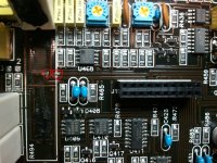
I had some more time to work on the amp tonight. There was a problem with no -14v to u409 and u408. It was a open via on the -14v trace running under the 10ohm resistor R494. The trace runs on the underside of the board between the two points circled in the picture. I just soldered a jumper wire through both vias and it everything went back to normal. You have to lift R494 to get to them. Here is a pic.
I'll ask the question in the next post.
Take Care,
Keith
Hello,
I had some more time to work on the amp tonight. There was a problem with no -14v to u409 and u408. It was a open via on the -14v trace running under the 10ohm resistor R494. The trace runs on the underside of the board between the two points circled in the picture. I just soldered a jumper wire through both vias and it everything went back to normal. You have to lift R494 to get to them. Here is a pic.
I'll ask the question in the next post.
Take Care,
Keith
Attachments
The question.
And the question is how do you check the bias on this amp? I checked other post, and it seems there is a jumper to remove. I don't see a jumper in this amp. I am assuming it is the offset pot in the picture. But where do you read the bias current (or voltage) for this amp. Sorry about the crappy pics, I used my cell phone.
Thanks for everybody's help
Take Care,
Keith
Attachments
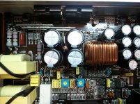
In general, there's no bias adjustment on class D amps. That's for class AB and class A.
The DC offset allows you to set the DC across the speaker terminals to as close to 0.000v as possible.
I'm not sure what the clip adjustment is for. It may be for the over-current set-point. Don't adjust it.
The DC offset allows you to set the DC across the speaker terminals to as close to 0.000v as possible.
I'm not sure what the clip adjustment is for. It may be for the over-current set-point. Don't adjust it.
- Status
- This old topic is closed. If you want to reopen this topic, contact a moderator using the "Report Post" button.
- Home
- General Interest
- Car Audio
- jl audio 250/1 repair