I've got a Soundstream 705S that is putting out 27.8V to my front right speaker channel. I've learned the hard way what this does to a speaker as it is right next to me when I am driving and the smell was awful before it finally cooked completely.
I've taken the amplifier cover off and cleaned the board as best I can with Q-tips and as far as I can see nothing is out of order (no bulged caps, burned areas or anything bad to the naked eye). I love this amplifier and built my system around it, but there is nobody in my area that I would send it to with confidence. I found some posts from the original amplifier designer (Wade Stewart?) who will repair it, but apparently he has "disappeared" in the last year or so and nobody can get in touch with him.
I've also come across an eBay seller (ampguy2004) who will do the repair for a flat $150 fee (plus my shipping costs) and he offers a 1 year warranty, but I'm hesitant to do so.
Is there a possibility that this is something that I can repair myself? I've been building PCs for 20+ years and am fairly handy with a soldering iron, but time is my major concern as I run a company and have a wife and kids that demand the rest of it. I would also take suggestions for sending it to someone that members are confident would repair it properly within a decent (4-6 weeks including shipping turnaround) time frame. I've got a Rockford Punch 600.5 (eBay purchase with a mildly crackly speaker output, but that's for another thread ) that will replace the Soundstream while it is being repaired, so I will still have music in my daily driver.
Any advice/suggestions would be greatly appreciated!
If you're going to send it to someone, I'd recommend Jaime (J&R electronics on ebay).
If you're new to amp repair, read the basic amp repair page (link in sig line below).
It may have shorted outputs. You need to check every one in the defective channel.
Do not remove it from the heatsink until it's necessary.
If you're new to amp repair, read the basic amp repair page (link in sig line below).
It may have shorted outputs. You need to check every one in the defective channel.
Do not remove it from the heatsink until it's necessary.
If you're going to send it to someone, I'd recommend Jaime (J&R electronics on ebay).
If you're new to amp repair, read the basic amp repair page (link in sig line below).
It may have shorted outputs. You need to check every one in the defective channel.
Do not remove it from the heatsink until it's necessary.
Thanks for the prompt reply, Perry. I've briefly went over some of the topics on your website and added it to my 'favorites' list to check on later once the kids are asleep.
I found reference to Jaime while perusing the forums earlier and did a search on eBay, but could not find anything. I would have no trouble sending it to him if he would agree to fix it.
I already removed it from the heatsink to inspect the bottom side of the board. I've got a large lighted magnifying glass mounted on a pivoting arm in my garage, I'll have to have a closer look with it to try and find any breaks.
Perry has the right advise, as always. Jaime is good people, I live just down the road a piece from him, and have done business with him for years now.
But just to touch base on possible failures, your likely looking at replacing the entire set of outputs for that channel to get a freshly matched set of of transistors of similar gain, and current sharing properties for reliability reasons {TIP102 & TIP107 transistor}. Also Jaime can supply you with the correct type FEB driver board that just solders into the main board and completely replaces the entire driver section of that channel. Jaime has all the parts you could want or need to do this.
Yes its just some simple soldering, but if your not use to this sort of thing you will likely need advise from one of us here or Jaime himself to complete the job correctly and to some level of expected success.
The tear down and reassembly will take longer then the actual repair by a fair margin and this is where care and attention must be given to not create anymore issues then those already addressed and repaired. I also suggest you buy some silicon heatsink compound for the reassembly so all the power devices get the best possible surface contact on reassembly. The compound is spread < sparingly> between the power devices and the Kapton insulator underneath the main board.
Also if you do it yourself the LED indicators on the top of the amp like to fight you on reassembly and often do not align up easily and end up not being presented properly at there thru case positions. A bit of back and forth may be required before you get this resolved to original... hope some of this helps.... I have done a many myself over the years....")
Here is Jaime :
http://shop.ebay.com/jandrelectroni...=1&_trksid=m194&ssPageName=STRK:MEFSRCHX:SRCH
But just to touch base on possible failures, your likely looking at replacing the entire set of outputs for that channel to get a freshly matched set of of transistors of similar gain, and current sharing properties for reliability reasons {TIP102 & TIP107 transistor}. Also Jaime can supply you with the correct type FEB driver board that just solders into the main board and completely replaces the entire driver section of that channel. Jaime has all the parts you could want or need to do this.
Yes its just some simple soldering, but if your not use to this sort of thing you will likely need advise from one of us here or Jaime himself to complete the job correctly and to some level of expected success.
The tear down and reassembly will take longer then the actual repair by a fair margin and this is where care and attention must be given to not create anymore issues then those already addressed and repaired. I also suggest you buy some silicon heatsink compound for the reassembly so all the power devices get the best possible surface contact on reassembly. The compound is spread < sparingly> between the power devices and the Kapton insulator underneath the main board.
Also if you do it yourself the LED indicators on the top of the amp like to fight you on reassembly and often do not align up easily and end up not being presented properly at there thru case positions. A bit of back and forth may be required before you get this resolved to original... hope some of this helps.... I have done a many myself over the years....
Here is Jaime :
http://shop.ebay.com/jandrelectroni...=1&_trksid=m194&ssPageName=STRK:MEFSRCHX:SRCH
Last edited:
After a read on the "Basic Car Audio Amp Repair" page, I took the amplifier out of the car (the bad channel was not hooked up) and had another look at it and tested the FETs. The readings are all over the place on all 4 of them. One of them has a different number than the other three and is obviously cooked, as well. It looks like a patch job was attempted by the previous owner (I've had the amp for about 10 years now).
Thanks for the link to Jaime's shop, I'll get in touch with him and see if he will fix it or supply me with the proper boards to take care of it myself.
There is already plenty (maybe TOO much!) of heatsink compound between the board, I spread it around to make contact a little more evenly when I had it separated. Is there a particular compound you would recommend? We use Arctic Silver for processor to heatsink on PCs, but I would need 10 tubes of that to take care of this job.
An externally hosted image should be here but it was not working when we last tested it.
An externally hosted image should be here but it was not working when we last tested it.
Thanks for the link to Jaime's shop, I'll get in touch with him and see if he will fix it or supply me with the proper boards to take care of it myself.
There is already plenty (maybe TOO much!) of heatsink compound between the board, I spread it around to make contact a little more evenly when I had it separated. Is there a particular compound you would recommend? We use Arctic Silver for processor to heatsink on PCs, but I would need 10 tubes of that to take care of this job.
You need to remove and replace all of the heatsink compound.
For this application, I recommend Dow Corning 340.
This amp has 8 power supply FETs. Were you referring to half of them or were you referring to the TIP102/107 darlington bipolar transistors?
What do you mean by all of the place? You need to be specific. Technical discussions require precise language.
I agree with Perry and just use simple silicon heatsink compounds. The Arctic silver stuff has fine metal dust in it and therefore it is actually electrically conductive and can short out electronics.
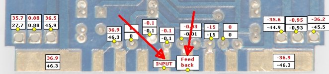
By the pictures you posted I see a repaired SUB channel that has smaller emitter resistors then stock and some FEB card damaged that was repaired. The other 4 channels typically used for the four corners of a car have circuit breakers on the outputs soldered to the board. I would test there for your DC voltage IF the amp was still in its sink... But since its already out now simple ohm meter testing should find open emitter resistors and shorted outputs for the bad channel in question.
Oh and the slide switches on these amps go bad due to moisture and contamination so count on testing them sonically and possibly replacing some or all of them. This is a very common issue with age on any of these particular series of car amps....
You need to remove and replace all of the heatsink compound.
For this application, I recommend Dow Corning 340.
This amp has 8 power supply FETs. Were you referring to half of them or were you referring to the TIP102/107 darlington bipolar transistors?
What do you mean by all of the place? You need to be specific. Technical discussions require precise language.
Sorry Perry, I was referring to the transistor with the A1479 marking and the 1 to the left and two to the right in the close-up shot (on the sub channel FEB cards) as I figured that must be at least partly responsible for my troubles as it is all blackened. After another 4 hours of reading and testing, it turns out all of these transistors on all six FEB cards seem to be fine (and the number on the transistor is correct as well). Either that or they are all damaged as they read the same across all 6 checks (transistortestpage01) in the diode check and ohms position on the multimeter. I'm doing my damnedest to take this slowly and read and reread pages of information, but it just seems to get more confusing as to what and where I should be looking.
1moreamp, I took the board out of the sink about 4 weeks ago when I did my initial check for physical damage. I then spread the heatsink compound out evenly and placed the board back onto the heatsink and secured it again. You are definitely correct about the switches getting dirty. About 6 months ago my front left speaker started cutting out at low volumes. I slid the switches back and forth a few times and it has been working fine ever since. Is it possible to reliably clean the switches with an electronic cleaning solution such as Deoxit?
Jaime replied to my email and said that he closed his repair business in 2008 and he now only sells components that he has left over. He does have the FEB boards (50-60 of them!) for this amplifier, but I haven't ascertained that the FEB board on this speaker channel is the issue. I'm thinking it might be prudent to purchase a few of them for future repairs as I don't imagine Soundstream makes them anymore.
"The other 4 channels typically used for the four corners of a car have circuit breakers on the outputs soldered to the board. I would test there for your DC voltage IF the amp was still in its sink... But since its already out now simple ohm meter testing should find open emitter resistors and shorted outputs for the bad channel in question."
So you are saying to hook up the amplifier again and check across the circuit breaker (I've traced the path back from the bad channel and found the circuit breaker) for DC voltage?
I'm not giving up yet, I'm planning on doing more reading on Perry's website tomorrow night!!
Another possibility is all transistors are fine (despite the dark marks on the PCB---heat over along period of time). Sometimes the solder of that upright daughter PCB is cracking.
Resolder all the solder joints that holds the daughter PCB to the main PCB. I've encountered many SoundStream amps that gives DC output just because of these cracking solder, nothing is broken.
Resolder all the solder joints that holds the daughter PCB to the main PCB. I've encountered many SoundStream amps that gives DC output just because of these cracking solder, nothing is broken.
Jaime replied to my email and said that he closed his repair business in 2008 and he now only sells components that he has left over. He does have the FEB boards (50-60 of them!) for this amplifier, but I haven't ascertained that the FEB board on this speaker channel is the issue. I'm thinking it might be prudent to purchase a few of them for future repairs as I don't imagine SoundStream makes them anymore.
"The other 4 channels typically used for the four corners of a car have circuit breakers on the outputs soldered to the board. I would test there for your DC voltage IF the amp was still in its sink... But since its already out now simple ohm meter testing should find open emitter resistors and shorted outputs for the bad channel in question."
So you are saying to hook up the amplifier again and check across the circuit breaker (I've traced the path back from the bad channel and found the circuit breaker) for DC voltage?
I'm not giving up yet, I'm planning on doing more reading on Perry's website tomorrow night!!
As for checking the circuit breaker well if you were to power the amp up for a few seconds you could test for the rail voltage at each breaker, that you say is present on one of your channel and then you would know exactly which outputs and FEB could be damaged.
You do enough of these and one tends to get into a rhythm about doing repairs to each brand of amp. SoundStream was prone to a typical set of failures so simple test methods while in the sink to localize troubles were my norm when dealing with one of these.
Simple DVM testing while powered up on a current limited variable power supply was first step and detection of errant voltages and DC offsets was number one. Switch testing was number two on the list, along with gathering of a set of replacement switches. Bad solder joints on the FEB boards was three. Once localized then board removal from sink was next so the repair could be completed and the re-assembly and test to SS procedures list.
Switch cleaning:
Well yes I have done this before, and found the old switches to be erratic in behavior, work sometimes and not another. I found them to need cleaning and also the bodies had loosened up and the contacts were intermittent. Now unless you enjoy removing and the tearing down and cleaning and reassembling these old switches I suggest you get Jaime to sell you a whole set and replace them and be done with them as possible rework issues. Yes switches can be saved but unless your use to repairing switches and the time sink of removal and re-install and retest, and sometimes repeat of this
step, then I say just buy new switches and replace them once, and hit the ground running not having second guess thoughts about any pesky little switch.
To be completely honest and up front to do the best job in as little time loss as possible just plan on gutting the defective channel by replacing the FEB card and all the outputs with same date code devices, and the MPSA13 Thermal bias transistor, and any out of tolerance emitter resistors. Once you have completed this simple and quick repair then you can concentrate on final test. This is where you find out if you missed something < very unlikely if you do a complete channel rebuild> and your back to some simple DC offset tests and voltage checking.
A complete FEB board and all new outputs will likely cost you around $20.00 to $30.00 US and you should have LIKE NEW operations without all the headaches of teching out each component, and possibly missing something. The latter will haunt you very shortly after you try to run the amp in real world.
Perry's tutorial, IMHO has to be the best training tutorial you will likely ever come across. But if your a one timer at this and want the job done quickly and completely correct then the simple method above might be for you. The parts are cheap enough, and the work simple enough requiring on simple soldering skills and some rudimentary DVM work. On the other hand if your educating yourself for the long term use of this sort of electronics tech level craft then please do not use the fast tech way above as this method is what experienced tech's working production level do for high speed and low rework situations, where Time Is Money....
To be completely honest and up front to do the best job in as little time loss as possible just plan on gutting the defective channel by replacing the FEB card and all the outputs with same date code devices, and the MPSA13 Thermal bias transistor, and any out of tolerance emitter resistors.
I thought this was a MPSA14 in most of the Reference series? Are the schematics wrong?
Rgs, JLH
- Status
- This old topic is closed. If you want to reopen this topic, contact a moderator using the "Report Post" button.
- Home
- General Interest
- Car Audio
- Soundstream 705S DC output...