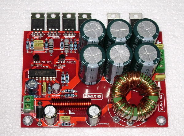
I bough two 180W, 12V to ±32V Power Supply Boards listed on eBay. One for $29 with shipping.
One powered up OK with no load, but the other one smoked as soon as I applied 12 V to the input terminals. The 12 V power supply was set to 2 amps current limit and the input voltage dropped to 4 V. The TL494 was very hot, so I need to get it out and check the drivers and FET’s. I charged the output caps to check for shorts, 3,300uF @ 35 V. I could send it back to Hong Kong for $10 postage, but that wouldn’t be any fun.
180W DC12V to DC±32V Boost Power Supply Board Kit 1PC | eBay
Did you have the transistors sinked, could they have overheated quickly or maybe they were just bad already. Either way, there aren't many parts to replace if you have to. :lol: Amazing what you can buy on fleabay.
No load and no heat sink, the first one worked fine and nothing got hot.
I pulled the TL494 and the 12 V current is now 6 mA. I pulled primary windings and replaced them with 12 V lights. I will bias each FET pair on one at a time. I have an old board with a TL494, but no new ones.
Last edited:
Confirm that you have ~5v DC on the gate pads of the FETs. Also confirm that the gate resistors are within tolerance.
I pulled 2 FET's and 1 PNP on one side, all three are bad. The other side witches the lamp OK without the TL494 installed. I will get a socket installed and a TL494.
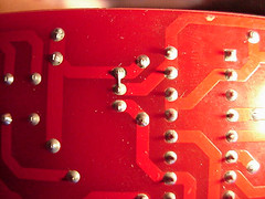
I received the parts to repair board #2, with new FET’s, TL494, PNP driver and diode it’s working. When I applied a load to board #1, I found it also had a problem, see pic for CE short of the PNP driver. This means neither board was tested at the factory with a load.
Last edited:
low cost = low testing, which would mean that you should be happy it even powered up once
Now I know, "SMPS NOT TESTED".
I wanted to let everyone know they should test the board with caution!
I'm happy.
Wayne
How hard would it be to modify this for use with an F5 board? Could you use one PS per board with a big heat sink?
Removing two or three secondary turns should reduce the output voltage to about 25 Volts. Check the output voltage and remove more or less to get the desired output voltage. One heat sink would work, the diodes generate more heat than the FETS.
- Status
- This old topic is closed. If you want to reopen this topic, contact a moderator using the "Report Post" button.
- Home
- General Interest
- Car Audio
- 12V to ±32V 180W SMPS