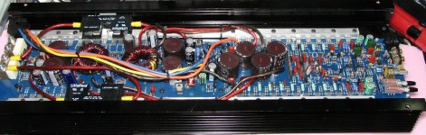
Ok I would like to start off saying I have spent about 14 hours over 3 days trying to find the answer to my puzzle. I have many of the pictures from the web saved which has helped but I need even more help.
I started repairing this amp 10 yrs ago when I was 16 then stopped b/c even though I didn't have much knowledge I knew that this amp was worth alot and I needed to stop while ahead. Now I have repaired over 100 amps since then and feel confident with my meter and scope I can work this out once I figure out exactly where everything I took off 10 years ago needs to go back.
Please excuse spelling and non-formatted text.
![IMG_0167[1].jpg](https://www.diyaudio.com/community/data/attachments/198/198609-e4a76fd345e9ee7291d31de2bec0462b.jpg "IMG_0167[1].jpg")
![IMG_0166[1].jpg](https://www.diyaudio.com/community/data/attachments/198/198627-76d9ebe0e67dc6b8dd3b149b8ff34ab3.jpg "IMG_0166[1].jpg")
![IMG_0165[1].jpg](https://www.diyaudio.com/community/data/attachments/198/198643-7ae54d930b69fcdfb70e235ea3c1ffbc.jpg "IMG_0165[1].jpg")
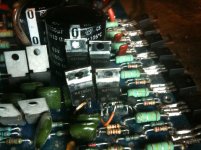
I have all of the parts I removed, I also found some new tip31/32 so I must have been on the right track not bad for being 16 and not knowing how to even test a transistor. I dont trust that the output rail that obviously I removed and re-soldered(poorly) has the transistors in the right place, and not sure which transistors to put in the empty spots on the other rail.
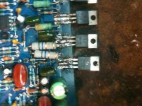
There are 4 output transistors that have never been removed (2N6491s?). There was one more of the same number next to those. The next 5 are the opposite polarity (2N6488s?). If you have one side correct, the emitters of the like-numbered outputs on the two sides will be connected together.
The base of the 6488 goes to the emitter of a NPN driver transistor. The base of the NPN driver goes to the collector of a PNP predriver. The basic circuit can be seen here:
http://www.bcae1.com/temp/orion01.swf
The values in the schematic will be a bit different but it should be close enough.
The base of the 6488 goes to the emitter of a NPN driver transistor. The base of the NPN driver goes to the collector of a PNP predriver. The basic circuit can be seen here:
http://www.bcae1.com/temp/orion01.swf
The values in the schematic will be a bit different but it should be close enough.
I just replaced the missing mpsu07/57 on the orange channel. I also am concerned the last two transistors on the output rail may need to swap positions. I fired it up it idles around 2.5 amps and the orange channel has 45vdc coming out with no input connected.
Attachments
Ok it appears that the voltage regulators are in the correct position. I replaced a few bad 1n4744 on each channel and now im getting 45vdc on the orange channels output and the voltage regulators on the yellow channel get hot really fast unclamped but the yellow channel plays clearly and seems powerful. The yellow channel is also missing a 2n6488 from its output at the moment.
Orange Channel
Pin 1: 7.56v
Pin 2: 4.0v
Pin 3: 3.5v
Pin 4: -12.55v
Pin 5: 9.5v
Pin 6: 10.8v
Pin 7: 13.1v
Pin 8: 13.0v
Yellow Channel
Pin 1: 12.13v
Pin 2: -0.2v
Pin 3: 0v
Pin 4: -14.1v
Pin 5: -0.6v
Pin 6: 0v
Pin 7: 14.5v
Pin 8: 12.1v
Sorry I was not even paying attention to the polarity on my meter it was slightly smudged with heat sink jelly. I also got a slighly different reading on pin2 of the yellow channel.
- Status
- This old topic is closed. If you want to reopen this topic, contact a moderator using the "Report Post" button.
- Home
- General Interest
- Car Audio
- Orion xtr-2250 Jigsaw puzzle please help!