The drawers i keep my parts in the 2A bjt's and A7 diodes are right next to each other. Somehow some A7's got mixed in with my 2A's and a A7 was installed in location Q119 when it should have been a 2A.
I have sorted through them and corrected the problem, note to self check the parts you are putting in to confirm they are what the drawer says they are.
Other than than that nothing. Still dont know why the protection transistors would cause distortion upon re-installing them (Q130 and Q126)
I have sorted through them and corrected the problem, note to self check the parts you are putting in to confirm they are what the drawer says they are.
Other than than that nothing. Still dont know why the protection transistors would cause distortion upon re-installing them (Q130 and Q126)
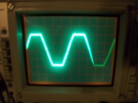
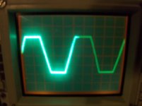
With Q130 installed the amp still produces clean audio, the first pic is before Q130 is installed and the second pic is after Q130 is installed. Looks the same to me but pic 2 I had a tad more volume so its a little more square.
Scope settings were 20 vol/div and 2ms. My probe is on 10x so I believe its 20 vol/div
Scope settings were 20 vol/div and 2ms. My probe is on 10x so I believe its 20 vol/div
Attachments
We'll have to troubleshoot that part of the circuit. Removing these two transistors did the same thing as removing the diodes Dx04, etc) in the later amps. It disabled the protection circuit. This allowed us to see if the problem was in the protection circuit or in the audio circuit.
Reinstall Q126 and remove Q120. Does the amp still produce clean audio?
Reinstall Q126 and remove Q120. Does the amp still produce clean audio?
We'll have to troubleshoot that part of the circuit. Removing these two transistors did the same thing as removing the diodes Dx04, etc) in the later amps. It disabled the protection circuit. This allowed us to see if the problem was in the protection circuit or in the audio circuit.
Reinstall Q126 and remove Q120. Does the amp still produce clean audio?
Yes it does with a nice signal on the scope as well. Q126 is back in and Q120 is out.
Well I just did a resistance check in ohms in all different probe configurations and it measures the same as a brand new one the only way I got any reading was black probe on collector and red probe on base and it was 17.54 M ohms.
I did replace 3 2L's in this channel with 2A's. I have several parts boards I can replace the 2A's back with 2L's maybe one of them failed?
The locations are Q135, Q136, and Q141.
Thoughts on those?
I did replace 3 2L's in this channel with 2A's. I have several parts boards I can replace the 2A's back with 2L's maybe one of them failed?
The locations are Q135, Q136, and Q141.
Thoughts on those?
Replaced Q135 Q136 and Q141 with 2L's from parts board and amp produces clean audio both channels with good signal on scope.
When I try to set the bias the current draw starts going up as soon as you turn the pots at all. This is not normal, usually you get at least 1/4 to 1/2 turn out of them before it starts drawing current.
Thoughts?
When I try to set the bias the current draw starts going up as soon as you turn the pots at all. This is not normal, usually you get at least 1/4 to 1/2 turn out of them before it starts drawing current.
Thoughts?
- Status
- This old topic is closed. If you want to reopen this topic, contact a moderator using the "Report Post" button.
- Home
- General Interest
- Car Audio
- Rockford Fosgate Punch 200IX