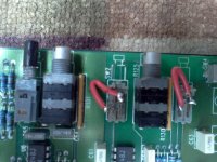
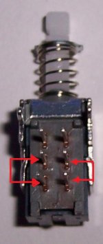
would anybody happen to know where to get the push buttons for the x-overs? in the first pic you can see one fully intact button & 2 broken buttons with wires soldered across the contacts. i picked it up from a guy a few months back on craigslist & i haven't even checked it out yet but i noticed the buttons missing. it's not absolutely nessecery but i would to have the amp in as nice condition as possible (for my collection).
thanks
thanks
Attachments
I used these PBH2UEEKZXNAG1RBLK from Mouser in a P840 and P4100 before. I just removed the metal shield.
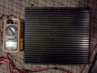
as of now im not getting any output from the amp. the power supply seems to be running fine and all the outputs are getting rail voltage but no signal. before i go any deeper ill probably wait on the new switches to get in and installed.
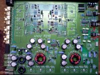
does anybody know if ads is affiliated with orion in any way? i just noticed a piece of an orion lable on the inner heat sink, it appears to be insulating the led leads from the heatsink.
does anybody know if ads is affiliated with orion in any way? i just noticed a piece of an orion lable on the inner heat sink, it appears to be insulating the led leads from the heatsink.
Attachments
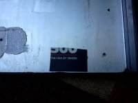
From the Directed site:
In 1994, Orion merged with ADS Technologies, pooling the resources of some of the leading home audio and professional equipment engineers in the world, resulting in products such as the DEQ30--the industry's first fully digital, standalone
30 band equalizer.
In 1994, Orion merged with ADS Technologies, pooling the resources of some of the leading home audio and professional equipment engineers in the world, resulting in products such as the DEQ30--the industry's first fully digital, standalone
30 band equalizer.
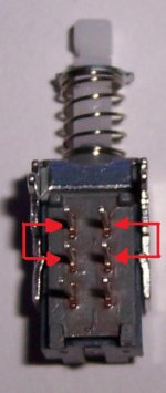
Remove the jumper wire it looks incorrect. The switch when pushed in (turning Crossover ON if I remember right) make contact like the first pic. The switch when out (turning crossover OFF) makes contact like the second. I may have it backward, but the wire should NOT jump accross the rows.
Attachments
Were there traces that went to the switch terminals on the top of the board under the switch?
If so, the vias to them may have been pulled which prevented getting a good connection to the switch.
Whenever you pull a component (especially if the board could be damaged), I'd recommend photographing the traces under the component before reinstalling it. That way you'll know which traces go to the various terminals and you can use a meter to check for continuity.
my mistake... the amp appears to work beautifully! when i was checking for an output signal i was touching my scope probe on the screws on the wire terminals. the problem is that the screws don't actually make contact with the outputs until a speaker wire is screwed into place. anyways all the crossovers and other preamp functions appear to work great along with the rest of the amp.
- Status
- This old topic is closed. If you want to reopen this topic, contact a moderator using the "Report Post" button.
- Home
- General Interest
- Car Audio
- ADS POWER PLATE P2110.2 20TH ANNIVERSARY