I got this amp who stopped working
when i opened it there was the trace from the ground terminal that was wide open on the board it shorted hard exactly between where the trace split in half.. the 2 fuses had blown also
I repaired the trace and replaced 2 P55NE06 that were shorted but i dont want to power the amp cause when i measure between the B+ and GND there is a resistance around 8K and i am not shure those 2 P55NE could have exploded that trace like that... it must have been a real hard short to blow away the trace from the board ...
what do you think about it
Last edited:
yeah thats what i will do i bought 8 anyways
the problem is that they sent me STP55NE06 instead of FP with a TO-220 non insulated casing ... so i wanted to use little mika's and screw insulators to isolate them from the heatsink... would it be ok ? they are rated at 55A instead of 30A
I wanted to check if the amp was working before changing them all..
I already checked the others are not leaking.. but i will change them all since they are all in parrallel and i have enough to replace them all...
is the 4K-10K resistance between the B+ and GND terminal normal ??
depending on wich sides i put my probes it reads around 10k or 4k
do you think the 2 blown FETs could have busted the track on the circuit and that only problem could be it ?
The trace was likely burned when 12v contacted the heatsink.
While you have the FETs out of the board, power up the amp and measure the DC voltage on the gate pads for the FETs. They should all read about 5v.
I wouldn't expect to read anything as low as 4k across the B+ and ground terminals but can't say it's not normal for this amp because that's not something I normally check.
With the FETs out of the board, what's the resistance across the B+ and ground terminals?
the resistance i am measuring is always rising or lowering slowly
now when i measure the B+ and ground terminal (with the FETs still on the board ill remove them after this message) i read 2k then going down slowly to almost 0 and then rising slowly up to 20K.. then i remove the probes and rechecked after moving the board closer to me ... and remeasured with the com probe on ground and V probe on B+ i measure 180K resistance and if i reverse them i measure 40K resistance...
what am i measuring exactly ?
am i charging something with the DMM .. the amp as been siting on a shelf for 6 months and the capacitors are discharged...
ok okay thats what i tought
so this is normal... allright
for the STP55NE06FP
is STP55NE06 a suitable replacement if i use insulator pads and tabs ? dont know if the thermal transfer will be as good... at least the STP55NE06 are rated higher...
do you have a part number or a name for those mika pads and screw shoulders? i dont know how they are called
I will have to try it out since i dont have the FP's
ill check to see if the clamping looks good after screwing them on the heatsink
for the washers/pads
whatever the company digikey or newark will be just fine ... it would help me a lot ill know the name/specs and everything needed to find it on Allied cause i dont know if they are called mika pads or shoulder tabs .. etc
its just cause i dont know the name for them i had 2 or 3 lying around at the job but now i need more obviously
nothing on mouser or anyother site i tried... even tried to search on google but nothing.. the only site that got me some results is the site i ordered from and then they called me to say they didnt had them anymore they only had the TO-220 version 
the only thing mouser tells me is a cross reference to NTE2953 and somebody i am talking to very often these days told me it was junk for amps
so ill guess i will go with the TO-220 case
the only thing mouser tells me is a cross reference to NTE2953 and somebody i am talking to very often these days told me it was junk for amps
so ill guess i will go with the TO-220 case
ok I replaced the power supply transistors and when i power the remote nothing happens it doesnt light up
so i checked the STP55NE06FP gate drivers and 0V on all of them (i forgot to check them when the transistors were out of the amp)
but anyways they all read 0V
I have checked if power was going to a few spots everything seems ok on what i have checked
there is 0.5V on the led... normal not to function if the power supply isnt working
what would you check ?
Last edited:
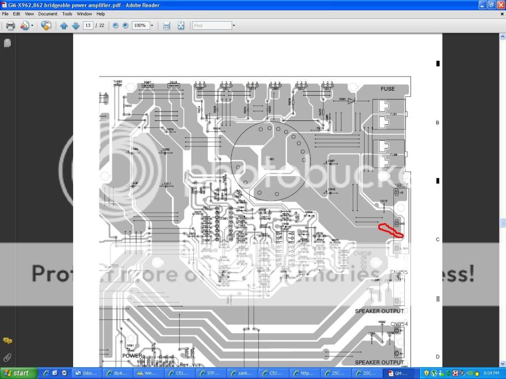
the 0.5v on the led comes from the left pin of Q660 (on the diagram) wich is a 2SB1243 and it also supplys IC901 wich is a UPC494C on pin 8 with 0.5v...
there is 13V going to the right pin of Q660 (on the diagram) directly from the fuses..
there is 13V going to one side of R671 (the side that connects to Q660 and the fuses) and about 11.8v on the other side wich connects to the middle pin of Q660 (on the diagram) this middle pin also connects to R672 wich has 11.8V on the Q660 side (of course) and has 0.25V on the other sides wich goes to IC651 pin #11
It's supposed to have essentially the same voltage on the collector and emitter when pin 11 of the 2027 is near 0v.
BJTs don't have gates. They have bases, collectors and emitters. You should read the transistor pages on the site. There were links to those pages on the basic repair page (which, hopefully, you've already read, at least once).
Shorting legs 1 and 2 of Q660 together should make the amp power up. It may, however, disable the protection circuit so have the transistors clamped and a 10-15 amp fuse in the B+ line.
yeah i know about BJT i just didnt take enough care to notice
i did a quick half a second 12V test on pin 11 and 12 of 494C and the led light up so its should be working ill clamp everything to the heatsink after my job and see if its outputing ... if it does ill replace Q660
do you think something else could have failed based on your knowledge?
i did a quick half a second 12V test on pin 11 and 12 of 494C and the led light up so its should be working ill clamp everything to the heatsink after my job and see if its outputing ... if it does ill replace Q660
do you think something else could have failed based on your knowledge?
- Status
- This old topic is closed. If you want to reopen this topic, contact a moderator using the "Report Post" button.
- Home
- General Interest
- Car Audio
- Pioneer GMX-962