Hi Perry
I have that RF BD1500 amp and it was doing great for the last years
last week i was driving a good song with some hard bass and all of a sudden it stopped working... it already happened to me once and it went into protect and was ok after 2 minutes but not this time ... it died and no protect led and no power led (the led in the middle to say its working)
but i can hear the amp wine a little as when it was working(always had that little wine when it was working... its not a ground problem or anything.. probably something inside the amp.. but not the issue for now..)
anyways so i tear it appart
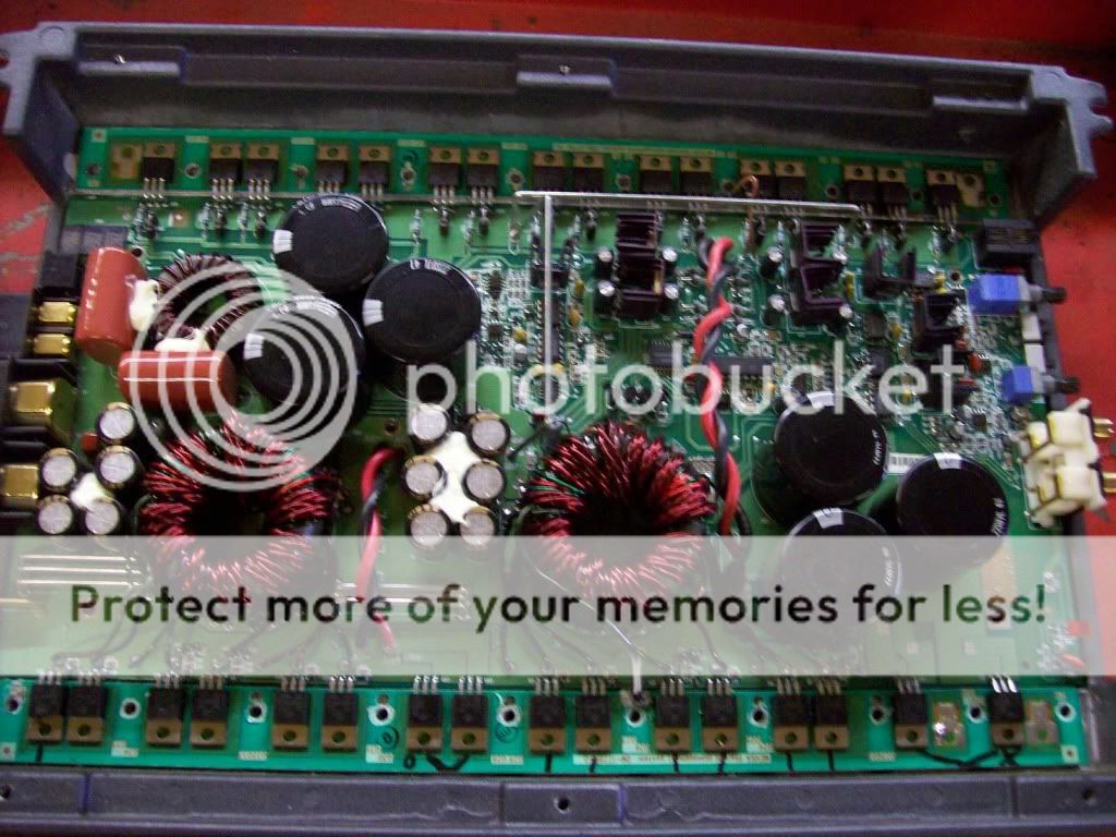
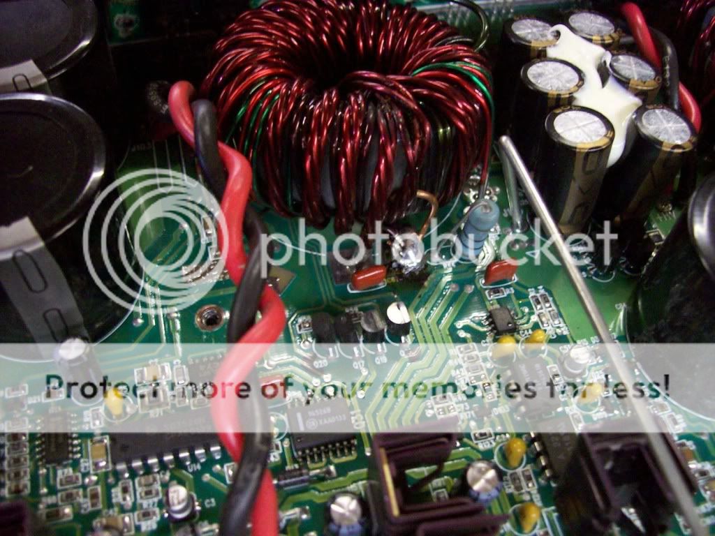
to find that the kind of coil/transformer wich is about in the middle of the amp (there are 2) the top wire had no coating left on it and it and it had shorted to the bottom cover (ill show you a pic)
then well.. i missmanipulated it putting it on my work table (with an aluminium outer edge.. and a part touched the edge and on transistor blowed in half.. ill show you also wich one..) so i fixed that one by resoldering the busted part to the board where is was going... it was blown at a nice place right at the last turn wich was then going to solder on the board where the big solder spot is with a bunch of wires coming there... so it is maybe missing like 3/4 inch now... i dont think this will make any difference for the length...
then i powered it
so there is the left coil/transformer(please tell me the name lol) wich is working and that is the part the wich is making a little wine when i press a little on it (probably my wine for the last 2 years) and this one is warm.. as well as the big resistance on the upper left of it so this looks like to be working... and when i look at the 2 transistors attached to the 2 BIG stack of wire of the "coil" i dont remember wich ones but they are 2 for each coil wich have 130V in the middle and ~60v on both sides wich the middle pin is connected to the 2 big twisted high voltage wires... well those 2 transistors show about 60V on tab 1 and 3 i think (the 2 outer ones) and the middle one is like 140 i dont remember exactly...
this is for the coil on the left wich is warm...
and on the right part...
the coil is COLD
the resistance is cold
and the 2 transistor if i mesure them it has the same 140v in the middle but nothing on both sides... (since they are all connected together.. the 2 high tension twisted wires) so i think the left working part is providing that voltage to the right non working part...
and i also check the 6 5N05HD going on both coils...
the left ones have an outer pin with 12volt and the other outer pin with 5v... alll of them... i dont remember the middle one...
and on the right non woring coil.. both the outer pins have 12v.... no 5v on all of the 6...
and the transistor i busted is the one on the upper right when you have the amp with the B+ and GND on the left side it is a IRF3415... it opened if half... that one is my fault but i dont think its that part that is not making the amp work of the right coil being warm...
I have that RF BD1500 amp and it was doing great for the last years
last week i was driving a good song with some hard bass and all of a sudden it stopped working... it already happened to me once and it went into protect and was ok after 2 minutes but not this time ... it died and no protect led and no power led (the led in the middle to say its working)
but i can hear the amp wine a little as when it was working(always had that little wine when it was working... its not a ground problem or anything.. probably something inside the amp.. but not the issue for now..)
anyways so i tear it appart
to find that the kind of coil/transformer wich is about in the middle of the amp (there are 2) the top wire had no coating left on it and it and it had shorted to the bottom cover (ill show you a pic)
then well.. i missmanipulated it putting it on my work table (with an aluminium outer edge.. and a part touched the edge and on transistor blowed in half.. ill show you also wich one..) so i fixed that one by resoldering the busted part to the board where is was going... it was blown at a nice place right at the last turn wich was then going to solder on the board where the big solder spot is with a bunch of wires coming there... so it is maybe missing like 3/4 inch now... i dont think this will make any difference for the length...
then i powered it
so there is the left coil/transformer(please tell me the name lol) wich is working and that is the part the wich is making a little wine when i press a little on it (probably my wine for the last 2 years) and this one is warm.. as well as the big resistance on the upper left of it so this looks like to be working... and when i look at the 2 transistors attached to the 2 BIG stack of wire of the "coil" i dont remember wich ones but they are 2 for each coil wich have 130V in the middle and ~60v on both sides wich the middle pin is connected to the 2 big twisted high voltage wires... well those 2 transistors show about 60V on tab 1 and 3 i think (the 2 outer ones) and the middle one is like 140 i dont remember exactly...
this is for the coil on the left wich is warm...
and on the right part...
the coil is COLD
the resistance is cold
and the 2 transistor if i mesure them it has the same 140v in the middle but nothing on both sides... (since they are all connected together.. the 2 high tension twisted wires) so i think the left working part is providing that voltage to the right non working part...
and i also check the 6 5N05HD going on both coils...
the left ones have an outer pin with 12volt and the other outer pin with 5v... alll of them... i dont remember the middle one...
and on the right non woring coil.. both the outer pins have 12v.... no 5v on all of the 6...
and the transistor i busted is the one on the upper right when you have the amp with the B+ and GND on the left side it is a IRF3415... it opened if half... that one is my fault but i dont think its that part that is not making the amp work of the right coil being warm...
I found some notes i had
the 5N05HD i was talking about voltages with both outer pins having 12v is wrong
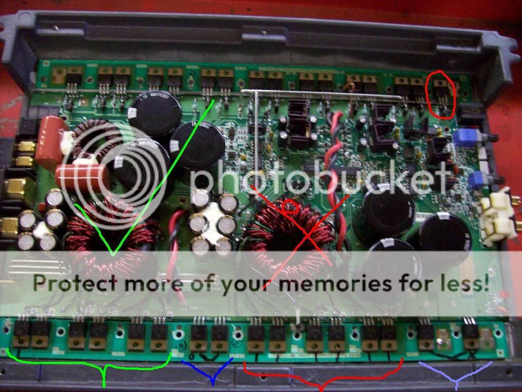
the 6 first 5N05HD's on the left (for the coil/transfo) (the corect ones i guess with a 5V gate) wich i marked with a green { on the left reads from left to right (if you refer to the position i took the left pic from)
GND | 13V | 5V
and from the right coil who doesnt work wich i marked with a red { they read
GND | 12V | 12V all six of them
I marked with a blue V the 2 working (i think) transistor (the ones that are not 5N05HD dont remember what they are)
and with a violet V the 2 wich has no 50-60V on both outer pins wich i think had something wrong... (i dont think its the actual transistor that are not woring... simply something before it wich go through...
i marked with a green check mark the coil and resistance that are warm wich are probgably working
and with a red X the one wich is ice cold .. nothing happening there... and i circled about where the copper wire had failed against the lower cover... (but on the pic its already fixed like i showed you on the last post... the black on that pic under the soldering is not a failure its only some flux/resin left from the soldering)
also on the upper right i circled the IRF3415 that i busted when the underboard touched the aluminium edge of my table...
hope things are more clear now")
the 5N05HD i was talking about voltages with both outer pins having 12v is wrong
the 6 first 5N05HD's on the left (for the coil/transfo) (the corect ones i guess with a 5V gate) wich i marked with a green { on the left reads from left to right (if you refer to the position i took the left pic from)
GND | 13V | 5V
and from the right coil who doesnt work wich i marked with a red { they read
GND | 12V | 12V all six of them
I marked with a blue V the 2 working (i think) transistor (the ones that are not 5N05HD dont remember what they are)
and with a violet V the 2 wich has no 50-60V on both outer pins wich i think had something wrong... (i dont think its the actual transistor that are not woring... simply something before it wich go through...
i marked with a green check mark the coil and resistance that are warm wich are probgably working
and with a red X the one wich is ice cold .. nothing happening there... and i circled about where the copper wire had failed against the lower cover... (but on the pic its already fixed like i showed you on the last post... the black on that pic under the soldering is not a failure its only some flux/resin left from the soldering)
also on the upper right i circled the IRF3415 that i busted when the underboard touched the aluminium edge of my table...
hope things are more clear now
It appears that both transformers have been rubbing on the cover. You'll need in insert spacers before you reassemble the amp. Thick fiber washers glued in place work well.
If I'm not mistaken, it appears that you took a wire that was going over the top and into the center of the transformer and re-routed it. If that's the case, it's likely creating a shorted turn and will cause the power supply FETs to fail after you replace them. If this is true, desolder the wire that you re-routed and soldered to the board.
The ones with 12v on their gates are blown and will need to be replaced. When you order replacements, order the replacement 10 ohm gate resistors (0805 size) and the drivers (MPSA06 and MPSA56).
The two large toroids are the power transformers. The small toroid is the output filter inductor.
What is the DC voltage measured directly across the red and black twisted pair?
Which transistor (Q7 or Q23) has 5v on leg 1 and which one has 12v on leg 1?
yeah ill glue a rubber washer on the transfo's before final assembly everything... would you hotglue it or epoxy it?
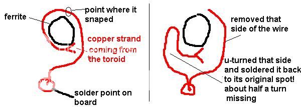
for the toroid (thanks for the name) wire .. the answer is no!! basically where the cover touched and the wire snapped .. one part was finishing its turn downward toward the spot where i soldered like crap (on the pic) and the other was coming from the toroid going inward the transfo on the top side... so what i did is trace back the lower wire to were it was soldered on the board... pulled it out.. cut it out.. and i took the other side coming from the transfo and u-turned it and soldered it back where it was originally... except it is missing like half a turn.. the top one that was going over and then under on the solder spot on the board... do you think that missing half a turn will change much ? (i did this cause it would have been a PITA to replace that only wire or the whole toroid wich would be hard to find and at first i wanted to make a patch with some other copper wire with coating the same size but i did not have any and it would have been weak... so thats what i did...
the transistors with 12v are definitely blown you say ??? it is not another component feeding some 12v to them instead of 5v? ... thats what i tought they had failed but i was not shure if the 12v was caused by them or something else...
if i remember corectly (its an aproximative) i can go and pick up the amp at my job if you need more precision... (if we need a scope it would be at my job so tell me ill stay there and not bring the amp back home)
the voltate with both probe wires on the black and red twisted wires was aroune 150 160V if i remember corectly ...on both of them since they are linked togeter on the board
the transistor with the 5v on leg1 (wich i think are working) are the 6 left ones on the bottom left wich are related to the left toroid... and then they are 2 HV transistors wich are connected to the 2 twisted black and red HV wires from the left toroid wich reads 50-60V on the 2 outer legs...
then after that there is the 6 transistors for the right toroid they all have 12v on leg1 and then the 2 last HV transistors for the right toroid wich have NO 50-60V on the outer legs...
so i remove the popped 3415 for now for testing purpose ? it will not affect testing but i need to remove/cut it ?
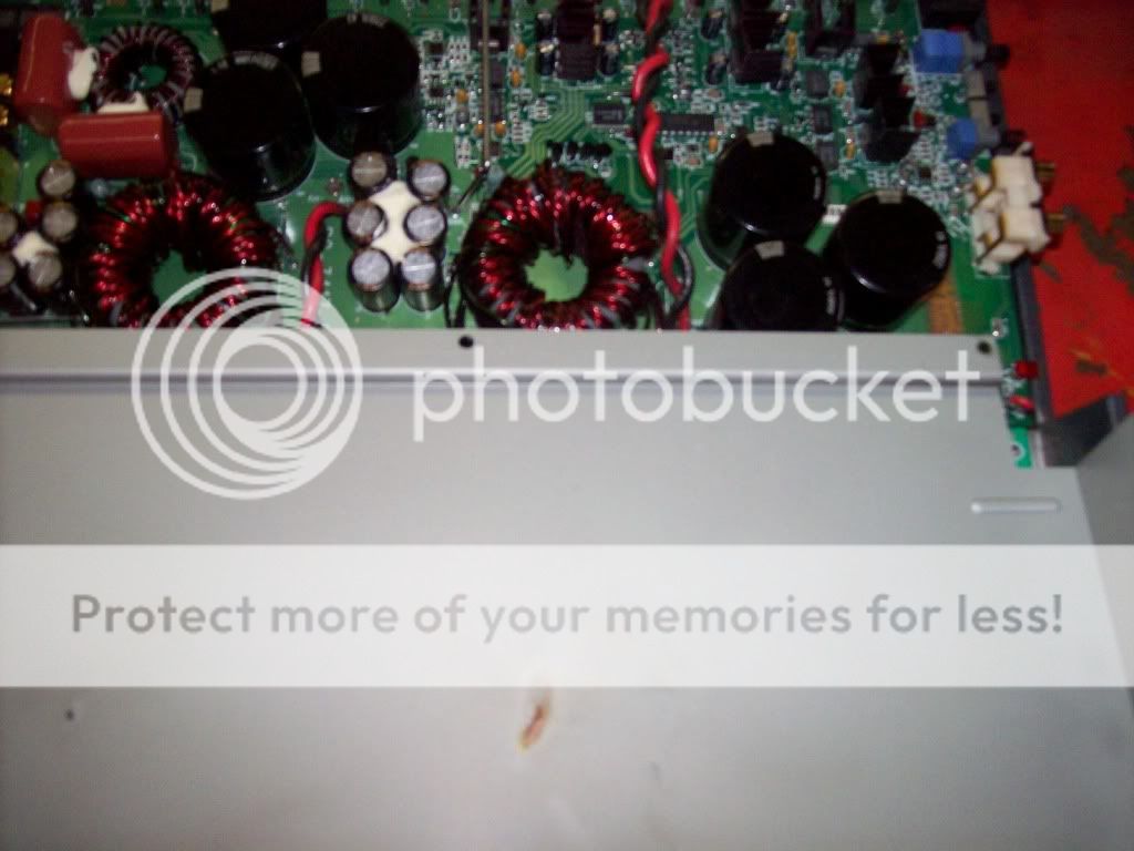
also on the left toroid i noticed when i say it is warm.. only the bottom side of the toroid is warm... not the upper side... maybe it is not in use for now and it is normal ... just tought i would let you know if it could help...
I did a pic to show what i did on the right toroid wire...
I did a pic to show what i did on the right toroid wire...
The washers go around the screw holes in the heatsink, not on the transformer.
The toroid is the round shape. They both use toroidal cores. The smaller one is an inductor. The larger ones are transformers.
Leave the broken wire unconnected. It's not ideal but it probably won't cause any problems. Replacing the transformer is the right way to repair it but I don't know if it's still available.
The power supply FETs with 12v on the gates are shorted internally. The 12v is coming from the inside of the transistor.
Cutting the blown 3415 out of the circuit will prevent it from causing other problems (if it hasn't done so already).
oh ok
so you put rubber spacer on the 6 bottom cover screw to space it from the transfos instead of putting something over the transfos to isolate them from the cover??
you think its better to leave the wire unconnected over resoldering it to its original spot ?? this means this is not what is making the amp not to work.. but when it shorted it may have damaged the power suply FETs right?
do you have a cross-reference number for the power supply FETs? cause i looked on NTE and they didnt have.. i have a bunch of transistors if i have something that fits it would be great... BTW do you have some yourself that you could sell me ? if you can
would you also happen to have a 3415 ?
I guess we cannot go further on diagnostics without replacing those components first?
Yes. You don't want the apply pressure to the transformer.
If you can re-connect the wire to the stub or extend it so that it can routed the way it was originally, you can solder it back in.
I'd suggest using IRF3205s in the power supply.
You can get both FETs from Digikey. You'll have to replace at least 4 of the 3415s.
The amp should power up and play if the only remaining problems are the power supply and the single 3415.
Never use NTE parts in car amps. They'll cause all sorts of problems and typically cost significantly more than the originals.
good advice for the nte parts thanks
usually its what i order as replacement parts but this time they dont cross reference!
for your IRF3415 replacement i looked at the IRF3205PBF on digikey and the 3205 continuous drain (id) seems way better at 110A instead of 43A for the 3415
but the drain to source voltage on the 3205 is much less at 55v instead of 150v on the 3415 is that one not that important ?
but why would i have to change at least 4 of them if only one blew ??(the one in the upper right corner)
did you made a mistake ? cause afterward on the other line you speak of the single 3415... lol
i tought i had to change 1 IRF3415 wich i blew up (upper right corner) wich you say i could use IRF3205PBF ?
and then change the 6 5N05HD on the bottom wich i would use FQP85N06 its the only replacement i found for those ones... (are they the power supply?)
allright i get you now
youre really me toward getting this to work... sorry if i ask a lot of questions i am educating myself at the same time and i want to be shure to understand it right do try and do it myself the next time... ill try to get as much questions as possible in 1 post so it is easier for you to answer with less messages!
so on the bottom is the power supply driving the transformers...
what is the purpose of the 3415 on the top ? (just to know)
and you said..
The amp should power up and play if the ONLY REMAINING problems are the power supply and the single 3415.
so in theory it should power up right now ? since you say that it should play IF i still have the remaining problems of the power supply and the single 3415 on top.. and it should work even if i dont solder back the wire to the transformer ?
that part i dont get ? are you saying it should power up and play for now even if i dont repair the power supply and the 3415...
btw how do you dissolder those bitches ? they are on the aluminum heat sink and when i go with my soldering iron (propane) it never dessolders cause of course there is way too much heat dissipation in the whole bar that it never dissolder.. how do you do it?
so for the 5n05hd i found FQP85N06 and IRF3205ZPBF as a replacement is this ok ?
and for the IRF3415 i found IRF3415PBF and IRF3415HR is this ok also ?
youre really me toward getting this to work... sorry if i ask a lot of questions i am educating myself at the same time and i want to be shure to understand it right do try and do it myself the next time... ill try to get as much questions as possible in 1 post so it is easier for you to answer with less messages!
so on the bottom is the power supply driving the transformers...
what is the purpose of the 3415 on the top ? (just to know)
and you said..
The amp should power up and play if the ONLY REMAINING problems are the power supply and the single 3415.
so in theory it should power up right now ? since you say that it should play IF i still have the remaining problems of the power supply and the single 3415 on top.. and it should work even if i dont solder back the wire to the transformer ?
that part i dont get ?
are you saying it should power up and play for now even if i dont repair the power supply and the 3415...btw how do you dissolder those bitches ? they are on the aluminum heat sink and when i go with my soldering iron (propane) it never dessolders cause of course there is way too much heat dissipation in the whole bar that it never dissolder.. how do you do it?
so for the 5n05hd i found FQP85N06 and IRF3205ZPBF as a replacement is this ok ?
and for the IRF3415 i found IRF3415PBF and IRF3415HR is this ok also ?
The 3415s and 6215s are used to produce audio. They don't produce audio directly but they switch the power that is eventually filtered and becomes usable audio.
If the 3415 is the only component on the top row that failed, the amp should produce audio. There is a very good chance, however, that at least one IRF6215 has also failed.
You'll need to use a torch to replace the transistors. Read the following page very carefully.
http://www.diyaudio.com/forums/car-...-schematics-3.html?postid=1901581#post1901581
The IRF3205ZPBF is a good sub.
I don't know what the HR part is. Use the IRF3415PBF.
its a similar welding iron that i have
basically you use it without any tip ? using the torch only ?
well its not producing any audio.. the ON led doesnt even light up... would a blown 6215 make the amp not even light up ?
I will check those too to be shure before i order up some parts on digi/newark... and i guess this would be the same as the 3415... if i have one busted 6215 i have to change a group so it matches?
any other cues on what i could check except that ? that you suspect could be toast ... or maybe a quick lookout here and there that you could suggest so that if i get bad news everywhere... maybe i wont put 50-100$ on parts to repair it to realise a bunch of other things are not working...
I had another replacement for 5n05hd wich the digikey site suggested me (FQP85N06) wich one would you take between that and irf3205Z?
Digi-Key - FQP85N06-ND (Manufacturer - FQP85N06)
Digi-Key - IRF3205ZPBF-ND (Manufacturer - IRF3205ZPBF)
Butane soldering irons generally have 2 tips. One is for soldering. The other is to use it as a torch.
If it has 100+v across the red and black wires, it's powering up. Which LED is the 'on' LED?
Measure the resistance across the legs of the individual output transistors (those along the top row). Do you read anything near 0 ohms between the legs of any individual transistor?
There's no guarantee that the amp can be repaired via this forum and mistakes may make the repair cost more than taking it to a repair shop. If you're looking for the quickest, least expensive option, you should pay to have it repaired. The repairs done through this forum are mainly for DIYers who would prefer to do the work themselves. You'll have to decide if you're willing to risk the cost of the parts.
its the led in the middle of the case at the end of the long 2 small twisted wires (the one wich lights the RF logo in the middle of the amp) its always been working until when it fails.. even if i check the voltage at the led wires on the board in case the led would have failed.. its a no go..
its the reason why i removed the amp and opened it
but it was like that before the top 3415 busted cause of me ...
then i opened it and found the transfo wire who shorted... and their transistors busted... but you seem to say that even with those power supply tnrasistors and the 3415 busted it should power on...
i ear the left transfo working and being warm but the ON light is not lighted.. (i will call it the on light lol)
yeah i can repair it i know that.. with your help there is no problem
Last edited:
ok so the 4 irf6215 for the LEFT bank doesnt show continuity between the legs (Q25,110,112,112)
iam giving you the components numbers written on the amp board itself not on the mesha termal management!
the 4 irf3415 for the left bank had 1.5Kohm resistance between leg 1 and 2 at first and all the other legs doesnt show continuity between them (Q8,104,105,106)
but when i had checked all the top row i started over to confirm everything and this time those 4 3415 on the left bank readed no continuity between leg 1 and 2... not 1.5K anymore
for the right bank its a different story
the 4 irf6215 for the right bank shows like this
Q109
pin 1 and 2 show 38ohm
pin 1 and 3 show 38ohm
pin 2 and 3 show 1ohm
Q108
pin 1 and 2 show 1ohm
pin 1 and 3 show 1ohm
pin 2 and 3 show 1ohm
Q107
pin 1 and 2 show 38ohm
pin 1 and 3 show 38ohm
pin 2 and 3 show 1ohm
Q26
pin 1 and 2 show 1ohm
pin 1 and 3 show 1ohm
pin 2 and 3 show 1ohm
then the 4 irf3415 for the right bank shows like this
Q12,101,102,103(103 is the one that i busted in half but i measured the reading on the board with Q103 legs cut out and its the same as the others)
pin 1 and 3 38ohm
pin 1 and 2 going from 2k to about 50ohm then going back up to 2k
pin 2 and 3 going from 2k to about 50ohm then going back up to 2k
i used the multimeter in ohm.. no diode check
- Status
- This old topic is closed. If you want to reopen this topic, contact a moderator using the "Report Post" button.
- Home
- General Interest
- Car Audio
- rockford fosgate BD1500 stopped working