Hi to everyone out there. Hoping someone can help. I know it seems common for these amplifiers to "fry", but I was am hoping to learn something and help this amp at the same time. I do have electrical knowledge but not a lot in electronics, so here it goes. I have read the posts here on the forum that pertain to some of the HCCA amps. I concentrated mostly on the post about the HCCA 250 that was grounding out. I tried to follow what Perry was asking the person to do but I do not know how much of the readings pertain to my amp since my amp is a 225 with an xtr275 board. It seems to me that the fets are consistent with each other but I don't know if they are consistently good or bad. The minute I turn on the amp with the remote, it blows. I mainly am looking for what the fets should read and other other transistors to look for. Thanks in advance. Scott
The K1542 FETS seem to test good. There are four 2n6491 on each side that seem good. I have four 2n6488 on one side and 3 on the other. I believe this amp has had a repair before because I have one 2n6487 in place of where the other side has an 88 in it's place. But they all seem test good. or at least no shorts.
As far as I could tell they looked original. I could tell on the fet that had been changed that it was not the original and these connections did not look like that. I do not have a resistor on hand or a headlamp. I do have a radio shack close by, I can see if they have one.
The Radio Shack part 271-120 can be used if you wire 4 of them in parallel. There's no guarantee that you'll be able to find the fault with the resistors but they can be used to find a few types of faults.
I'm sure that the rectifiers are OK if they only read shorted between the outer terminals when in the board but you should check them before you do anything else.
I'm sure that the rectifiers are OK if they only read shorted between the outer terminals when in the board but you should check them before you do anything else.
You'll reinstall them.
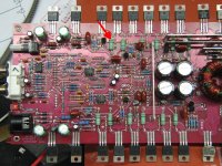
With the 2 ohm resistor (four 8 ohms in parallel) in series with the B+ line (in place of the fuse), you'll power up the amp and measure the DC voltage across every one of the large resistors near the output transistors. All of them should read 0.000v DC. If any one or group of resistors reads higher than 0.000v DC, there is a problem.
You'll have to have all transistors clamped tightly to the heatsink when doing this.
Ok so I built a circuit with four 8 ohm resistors in parallel. I put a spade connector on each end of the wire to insert into the fuse holder ( hopefully you can visualize it ). basically a 2 foot piece of wire bent into a u shape with the resistors soldered between the wires running parallel to each other. So if this sounds correct, which large resistors will I be taking the readings from. Are they green. I am not familliar with where the output transistors are. Thanks, Scott
So I took the resistor that read .01v out of the circuit. The only real change was that the resistor to it's left which had read .35v before jumped up to .42v. So I took that one out also and the resistors read as follows, .002v, .001v, .001v, .001v. Now I cheated and only lifted one side of the resistors that I took out of the circuit. I would think this would be the same as taking them completely out. So I will take the one that reads .002v out and see if this changes anything. I will publish my next results if this changes the others down to .000v. Please let me know what you think next. Thanks
- Status
- This old topic is closed. If you want to reopen this topic, contact a moderator using the "Report Post" button.
- Home
- General Interest
- Car Audio
- Orion HCCA 225 digital reference blows fuse