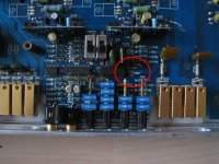
Hi all, got a replacement board for my project Continuum, board needs a bit of work and currently working on the PS side of things, the PS seamed fine before i replaced C907 and C908 and then started drawing big current!
i bought the board as faulty board and someone has already taken parts out and such, needs outputs/driver boards and the like but stripped all the bad ones out for now..
i bought the board as faulty board and someone has already taken parts out and such, needs outputs/driver boards and the like but stripped all the bad ones out for now..
Attachments
Do you believe that the caps were the problem?
I don't see any pads in the photo. Were they SMD caps?
Are you sure that capacitors were supposed to be there?
yes, i have my other (really blown!) spare board here i'm using for reference/spares, they are little yellow caps and one blew as well. i've now removed the caps and a further bad FEB. the amp turns on and straight away pulls around 6amps then declines to a turn off very fastly (not in protection, just nothing)
got a schematic here if you havn't got one? i noticed the fen16dt's have been sub'd out for NTE6244, not sure if this is correct??
Mark.
I don't have the diagram. Please send me a copy.
Are the caps that you installed shorted?
Can you post a clear photo of them? Set the camera to super macro (hold the macro button down for a few seconds).
it's actually the schematics for the 705s but so far i don't see any difference in board layout of parts.. i'll sort out the close up pic later after work
")
not sure how ro send the document to you but my email addy is markshutt70 (at) gmail.com
they're located on page 2 of the schems and to the right next to an IC which has something to do with the sub channel? maybe i should strip that channel out and go from there?
it's very strange as i'm one step back from where i was before i re-installed those 2 caps! (amp won't even stay on now)
it's very strange as i'm one step back from where i was before i re-installed those 2 caps! (amp won't even stay on now)
Are the rectifiers still out of the amp?
there is one (out of 8?) still out, think it's a fep16dt, didn't think it would matter too much just for testing purposes as they are parallel paired?
i still don't get how it turned on fine before i installed the caps then nothing now, think i've done more damage somewhere
If it was powering up normally with the rectifiers in the amp as they are now, power up the amp and post the voltage on all of the terminals of the 3524. Post the voltage before and after it shuts down.
Pin 1:
Pin 2:
Pin 3:
Pin 4:
Pin 5:
Pin 6:
Pin 7:
Pin 8:
Pin 9:
Pin 10:
Pin 11:
Pin 12:
Pin 13:
Pin 14:
Pin 15:
Pin 16:
Pin 1:
Pin 2:
Pin 3:
Pin 4:
Pin 5:
Pin 6:
Pin 7:
Pin 8:
Pin 9:
Pin 10:
Pin 11:
Pin 12:
Pin 13:
Pin 14:
Pin 15:
Pin 16:
hard to get a before reading as it more or less does not want to power up!
Pin 1: 5v
Pin 2: 2.5v
Pin 3: 200mv
Pin 4: 0.4mv
Pin 5: 0.2mv
Pin 6: 3.45v
Pin 7: 2.1v
Pin 8: .2mv
Pin 9: 50mv
Pin 10: 19mv
Pin 11: 1.2mv
Pin 12: 12v
Pin 13: 12v
Pin 14: 6.3v
Pin 15: 11.23v
Pin 16: 5v
Pin 1: 5v
Pin 2: 2.5v
Pin 3: 200mv
Pin 4: 0.4mv
Pin 5: 0.2mv
Pin 6: 3.45v
Pin 7: 2.1v
Pin 8: .2mv
Pin 9: 50mv
Pin 10: 19mv
Pin 11: 1.2mv
Pin 12: 12v
Pin 13: 12v
Pin 14: 6.3v
Pin 15: 11.23v
Pin 16: 5v
Last edited:
Does it have a thermal switch (TS2) on the bottom of the amp?
One terminal would be connected to R171. The other terminal would be connected to ground.
yes it does, also has another one (TS1)
I'd expect pin 1 to be lower if the switch and the associated components were properly connected. Is there a broken trace between TS2, R171, pin 1 of the 3524 or ground?
If you ground pin 1 (connect to pin 8 with a short jumper wire), does the power supply power up?
If you try this, have all transistors clamped tightly to the heatsink and have a 10-15 amp fuse in the B+ line.
If you ground pin 1 (connect to pin 8 with a short jumper wire), does the power supply power up?
If you try this, have all transistors clamped tightly to the heatsink and have a 10-15 amp fuse in the B+ line.
- Status
- This old topic is closed. If you want to reopen this topic, contact a moderator using the "Report Post" button.
- Home
- General Interest
- Car Audio
- trouble shooting Soundstream Continuum.