All of the fets were defective in this amp (IRF1404) . I removed them and between pads 1 and 3 i have 15 ohms.
I believe the driver is a IR2010 Ic.
With the ic in the amp pads 1 and 3 connect to pin7.
From pad 1 to pin7 i get 10 ohms
From pad 3 to pin7 i get 5 ohms.
Is this normal or is the IC likely defective?
I believe the driver is a IR2010 Ic.
With the ic in the amp pads 1 and 3 connect to pin7.
From pad 1 to pin7 i get 10 ohms
From pad 3 to pin7 i get 5 ohms.
Is this normal or is the IC likely defective?
Do you have an oscilloscope? With the power MOSFET's removed, you can apply power and look at the gate drive signal. I don't know this amp, but all the one's I've played with and built use a separate control IC (e.g. a TL494), and you should be able to probe the outputs of that if you're not getting anything from the mosfet driver. I wouldn't bother trying to look at resistance of the IC's unless that's all you have to measure with.
Are you sure it's in IR2010? These are a High & Low side mosfet driver, it would be unusual for a high side driver to be employed in a car amp, as the voltages are too low to make a full bridge configuration any use, in fact it would be quite a pain. Normally they are all push-pull configs that use just dual low side drivers.
As for your stuffed mosfets. Just be aware that blown power mosfets in a switchmode power supply is a given when almost anything goes wrong. It really is very little help in narrowing down what the cause of the problem is. So be sure to look thoroughly at the output side of the transformer and what else could potentially have gone wrong i.e. overloaded the supply.
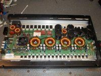
This is similar to the Stetsom amps. The PIC is used to do everything but it doesn't have the ability to drive the FETs. They use a different driver in the Stetsom amps. They're likely only using the low side drivers in this IC since it appears that all of the sources of the FETs are grounded.
Pull the driver IC and measure the resistance again.
Pull the driver IC and measure the resistance again.
Hold on a sec... For the irf1404 (TO220AB package)...
LEAD ASSIGNMENTS
1 - GATE
2-DRAIN
3 - SOURCE
4(tab) - DRAIN
Just check we're all talking about the same leads here as per the IRF datasheet.
This doesn't sound completely right. The most useful thing for you to do would be to grab a pencil and paper, the looking at both sides of the PCB, draw up a basic schematic of all the main power devices, transformers, IC etc with pins marked IAW the datasheet. This is a very powerful technique to understanding what's going on. I use it when I can't quite get my head around what a designer has done, and usually it all falls into place. From there we can provide much better assistance when we know exactly what your measurements are connecting to...
Perry, your post about the pic just popped up.
Please enlighten me about what they do as I haven't had the honour to dismantling an amp with a micro in it yet! i.e. does it just do PSU control and protection or does it go as far as including some of the amp functions as well (class D)?
I've got plans for another amp using the AVR PWM range of controllers.
They use the PIC in the Stetsom amps for protection logic and square wave generation for the power supply. This includes a soft start, of sorts. They go from 0-50% duty cycle in about 5 steps. The PIC in the amps I've seen had far fewer pins so this amp may do more with it.
http://www.stetsom.com.br/Uploads/Downloads/1862009114242805.pdf
This is for a stetsom amp. Does the flashing of the red LED match what's shown on the error table?
This is for a stetsom amp. Does the flashing of the red LED match what's shown on the error table?
- Status
- This old topic is closed. If you want to reopen this topic, contact a moderator using the "Report Post" button.
- Home
- General Interest
- Car Audio
- Sound Digital 8K