So I put this thing back together and tested it's audio output but it seems 1 channel is very distorted.
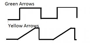
I drive a square wave through it and at low level it looks fine but as you increase the volume it turns into a sawtooth wave form as the top of the wave squeezes together until it is just a point. I found this on the emitters of the distorted channel and it is also present on the drive resistors.
Where should I look first?
Honestly, I don't have a generator to produce a sin wave.
The other channel handles it perfectly.
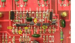
Here's a pic from your tutorial, the driver sections aren't exactly the same but they are very similar.
The yellow arrows indicate where I see it turn to sawtooth and the green arrows are where it is a clean square.
Does that help much?
The other channel handles it perfectly.
Here's a pic from your tutorial, the driver sections aren't exactly the same but they are very similar.
The yellow arrows indicate where I see it turn to sawtooth and the green arrows are where it is a clean square.
Does that help much?
If you have the tutorial, navigate to the following file and confirm that it's the same as the one you have there. The QA/QB will be different but confirm that the values of the other components' designations match.
/repair_tutorial/miscellaneousstuff/audiobahn/unknownaudiobahn01.swf
If you have the tutorial, you have a test tone CD with sine waves.
/repair_tutorial/miscellaneousstuff/audiobahn/unknownaudiobahn01.swf
If you have the tutorial, you have a test tone CD with sine waves.
I have the test tones but do not have a CD player in my work area, my computer is in the living room so I can't use it either. I will buy a little cheapy cd player/alarm if I can't resolve this otherwise.
I will check the values tomorrow, I'm not at home at the moment. Thanks a bunch, though.
I will check the values tomorrow, I'm not at home at the moment. Thanks a bunch, though.
Ok, the way q2 q3 q4 and q5 are tied together is the same but, for example, RA44 on the schematic shows a .1/5w, in this amp RA44 is tied driving the base of an output transistor.
It also seems that some of the parts shown in the schem. aren't in the amp and vice versa. The bulk of the scematic is very similar, though.
It also seems that some of the parts shown in the schem. aren't in the amp and vice versa. The bulk of the scematic is very similar, though.
Here is what I see when the oscope probes are on the arrows shown in the first picture. With the gain all the way down the waveforms are identical, when you start to turn it up they start to distort in this manner. Only one channel does this, the other works perfectly.
Attachments
Last edited:
/repair_tutorial/miscellaneousstuff/maaudio/maaudio01/P1010008.jpg
Never had to locate the muting transistors but I believe QA1 and QB1 in the above image (KSP26s) are the muting transistors. Please correct me if I'm wrong.
The waveform on one of them looks totally different than the other (on center leg). Also, the one associated with the distorted channel (QB1) is getting warm while the other (QA1) stays at room temp.
Last edited:
- Status
- This old topic is closed. If you want to reopen this topic, contact a moderator using the "Report Post" button.
- Home
- General Interest
- Car Audio
- MA HC4002, powers up but audio is distorted