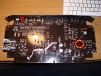
Its been a while since I last posted on this forum, because Perry Babin has taught me so well that I managed to fix some amps on my own. Yesterday I bought myself a new toy: FLI Loaded 400s amplifier. Bought it from online auction, seller claimed that capacitors needed to be replaced, I thought he meant to write transistors and bought it. It is much worse than I expected: 6 transistors and one rectifier are missing.
The rectifiers are MUR1620CT and MUR1620CTRG, 1620CT is missing. 1620CTRG is soldered to board so badly that all three pads are bridged. Interesting what kind of damage amp suffered if someone tried to switch it on in that state? How can I be sure that CTRG is where it is supposed to be?
Two of the missing transistors are output transistors: 2SB778 and 2SD998. Again, how do I know which goes where?
All of the 4 FETs are gone, how can I make sure which ones I need? I recently fixed FLI loaded 200s amplifier, it had a shorted FET. That model used IRFZ44N, is it a reasonable thought that these FETs would be suitable for this amp as well?
Thanks in advance for good advice!
Attachments
Last edited:
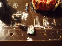
The center leg of the CT goes to the positive terminal of the rail caps. The center leg of the CTR goes to the negative leg of one of the rail caps.
If the emitter resistors of both the 2SB and the 2SD transistors connect together on the board (for each channel), the center leg of the 2SD output will go the the center leg of the CT rectifier. The center leg of the 2SB output will go to the center leg of the CTR rectifier.
The gate resistors appear to be 51 ohms. If that's true, the Z44s will be OK.
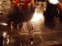
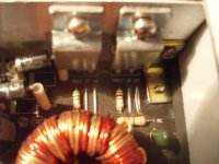
The resistor on the left is not a gate resistor, but on the right, the blue one, is gate resistor and it measures also 1k ohm. I think I need to replace it with 51 ohm resistor?
I bought four IRFZ44N FETs, 2SB778 and 2SD998 transistors, but did not manage to get MUR1620CT yet - local store does not have them in stock.
Inserted two IRFs on the board where gate resistors were both 51 ohms. Removed the rectifier diode. Clamped the board to heatsink and switched the power supply on. Measured 4.3 volts between gate and source on these IRFs. That means so far so good?
If it's an option for you:
BG-Electronics
They have them in stock.
They have a minimum order of only 10€ and fair shipping fees.
But I don't know how much it is to Estonia...
BG-Electronics
They have them in stock.
They have a minimum order of only 10€ and fair shipping fees.
But I don't know how much it is to Estonia...
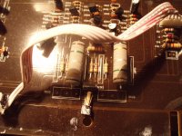
Finally got all the spares needed for this amp. Inserted two of the missing IRFs replaced the resistor, switched it on. I used 12v lamp as a current limiter, it did not light up but glowed a little bit. Switched power supply off, checked board for solder bridges but everything seemed to be OK. Then tried to switch it on again, this time lamp did not glow. Then I inserted rectifier diodes. Power LED turned on lamp did not glow but after 10-20 seconds two IRFs that I inserted earlier blew. I did not replace CTR rectifier diode because it seemed to be fine, checked it with multimeter diode check. Two of the missing output transistors I did not insert and those already on the board were OK. If they werent then lamp would have lighted up at once after inserting rectifiers?
After switching amp on first time i had the feeling that IRFs that I inserted today got hotter then the others, is that normal? 51 ohm resistor is supposed to be 1W but I had to use 3W resistor but that can not do any harm?
Heatsink is very badly designed on this amp, board needs to be bolted to the heatsink and those bolts are missing so the transistors were only resting on, not clamped to heatsink, maybe that was why IRFs failed? But why the other two IRFs do not get hot?
Removed all PS FETs. Measured 4.01-4.08 volts on each gate solder pad. I also measured voltages on 2nd and 3rd leg solder pads. On 3rd leg solder pads 0 V on each of them. Here it gets interesting for me: 2nd leg pads for the two IRFs which did not fail: 0.18 V but 2nd leg pads for IRFs which failed: 12,2 V
")
Got some more IRFZ44Ns, installed them. Powered the amp and again current limiting lamp started to glow, turned amp off. Resoldered transformer leg still did not give contact all the time. Resoldered it again, this time I did not hold myself back and after that amp works and produces audio.
Thanks again Perry.
Thanks again Perry.
- Status
- This old topic is closed. If you want to reopen this topic, contact a moderator using the "Report Post" button.
- Home
- General Interest
- Car Audio
- FLI loaded 400s amp missing some transistors