This amp powers but does not play. The test speaker presents the pretty standard Class-D low amplitude white-noise but nothing more.
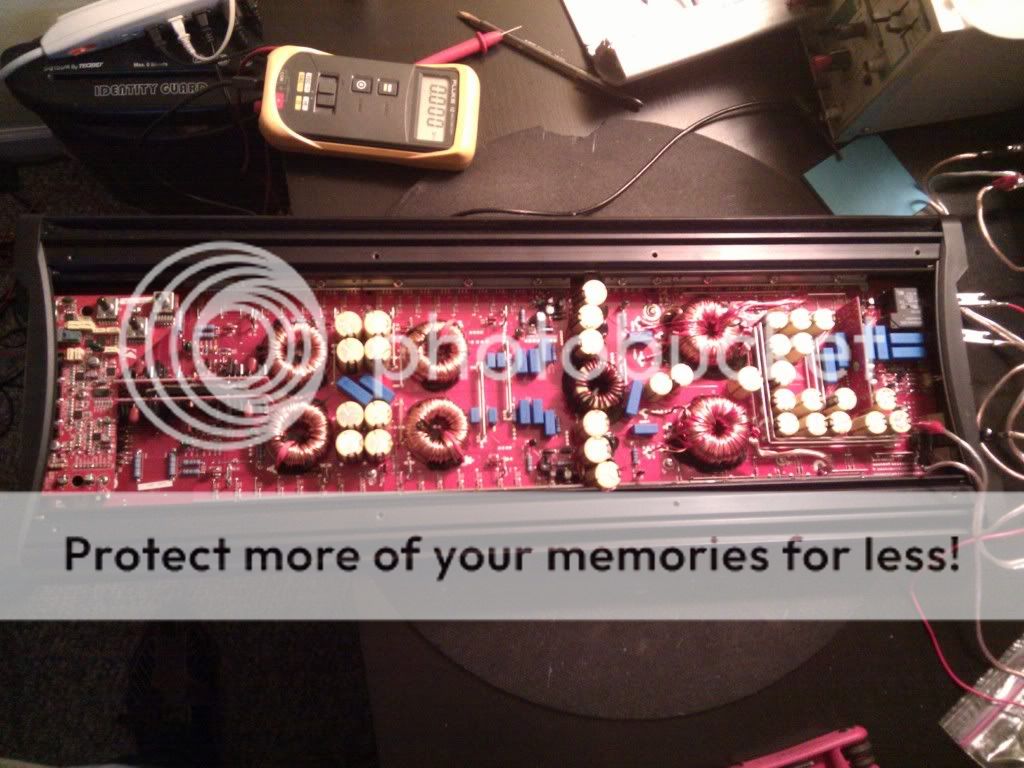
The amp is in great shape and has never been opened. There are no burned components inside to speak of.
The rail voltage is +-62vDC referencing general ground.
The opAmps on the pre-driver board 9Left of photo) all measure +-12vDC on the power pins referencing amp general ground.
After a few minutes, vertical driver boards get warm but touchable.
I tried swiveling the gain pots and controls to no avail. The quiet sound of the sea out of the test speaker does not change.
I'm about to take it fully appart, but past experience with this type of thing tells me it might be simpler than something hidden under the PCB.
Resistence on RCA shields is 40k just about everything on the board including speaker terminal outs and amp ground. Im not sure where secondary center tap would be on this amp.
Why wont this amp make sound?
Last edited:
WOW this is a big amp. Possibly one of the most costly I've repaired as well. Kicker MSRPs this bad boy for ~$1,400. Its Class D Monoblock, 2500x1 at 2 ohms. WOOW.
This amp has 20x IRF3205 transistors 12x IRF640, and 20x IRF9640.
I need to get this thing fixed lol!
I pulled the board out of the sync. Darn; no signs of trace damage...
This amp has 20x IRF3205 transistors 12x IRF640, and 20x IRF9640.
I need to get this thing fixed lol!
I pulled the board out of the sync. Darn; no signs of trace damage...
Last edited:
I'm not exactly sure which one of these pins transmits the audio to the main PCB. The 9 pins are labled as pictured. Starting fro mthe bottom which appears to be Pin1 - REMBAS - I measure the following DC voltages referencing amp general ground:
Pre-Amp board pins:
Pin 1: 10.51 labeled REMBAS
Pin 2: 0.005 labeled GNDS
Pin 3: -11.75 labeled -12v
Pin 4: 12.00 labeled +12v
Pin 5: 0.005 labeled GNDP
Pin 6: 13.36 labeled +BATT
Pin 7: 13.41 labeled REMOTE
Pin 8: -19.84 labeled MUTE
Pin 9: -10.61 labeled SUB_IN


Pre-Amp board pins:
Pin 1: 10.51 labeled REMBAS
Pin 2: 0.005 labeled GNDS
Pin 3: -11.75 labeled -12v
Pin 4: 12.00 labeled +12v
Pin 5: 0.005 labeled GNDP
Pin 6: 13.36 labeled +BATT
Pin 7: 13.41 labeled REMOTE
Pin 8: -19.84 labeled MUTE
Pin 9: -10.61 labeled SUB_IN
Q101 and Q102 are measuring 50 ohms from legs 1-2. They are M09 transistors, or PMBFJ309.
Datasheet:
http://www.nxp.com/documents/data_sheet/PMBFJ308_309_310.pdf
Pin 1 is source, Pin 2 is drain.
Are these bad perhaps or are they muting circuitry?
Datasheet:
http://www.nxp.com/documents/data_sheet/PMBFJ308_309_310.pdf
Pin 1 is source, Pin 2 is drain.
Are these bad perhaps or are they muting circuitry?
Do you have clean audio on the output pin of the preamp board?
I think I found a good center-tap reference. From there, I find audio signal comming off most of the opAmp outputs on the pre-amp board. There is no audio on any of the pre-amp's pins leading to the primary pcb.
Here is where I'm thinking secondary center tap is on this amp. its ~2ohms to general ground.


U107 has -10vDC on all pins except but pin 8, which has +12
U106 has +-12vDC on the power pins, and -10vDC on pins 6 and 7.
The other opAmps have ~0vDC on all output pins
U106 has +-12vDC on the power pins, and -10vDC on pins 6 and 7.
The other opAmps have ~0vDC on all output pins
An externally hosted image should be here but it was not working when we last tested it.
Last edited:
I removed U107 and powered the amp up. The pads under U107 are measuring as follows:
Pin 1: 0
Pin 2: 0
Pin 3: -12
Pin 4: -12
Pin 5: 0
Pin 6: 0
Pin 7: 0
Pin 8: 12
U106 is still in place. Its measuring as follows:
Pin 1: 0
Pin 2: 0
Pin 3: 0
Pin 4: -12
Pin 5: 0
Pin 6: -12
Pin 7: -12
Pin 8: +12
Would -12 on Pin 6 of U106 make it defective?
Pin 1: 0
Pin 2: 0
Pin 3: -12
Pin 4: -12
Pin 5: 0
Pin 6: 0
Pin 7: 0
Pin 8: 12
U106 is still in place. Its measuring as follows:
Pin 1: 0
Pin 2: 0
Pin 3: 0
Pin 4: -12
Pin 5: 0
Pin 6: -12
Pin 7: -12
Pin 8: +12
Would -12 on Pin 6 of U106 make it defective?
When op-amps are used for audio, they virtually always work to make the inverting input have the same voltage as the non-inverting input. Since pin 5 (the non-inverting input) is at 0v, the op-amp should drive the output to bring the inverting input (pin 6) to 0v. Since it isn't doing that, it's likely defective. I'm assuming that nothing (external to U106) is driving the output to -12v.
I'd say we nailed it.
Since its tough without a schematic to really see what was driving the inverted input pin 6 to -12v, I used process of elimination.
Removing U106 revealed the following pad voltages measured with the DVM
U107:
Pin 1: ~0
Pin 2: ~0
Pin 3: ~0
Pin 4: -12
Pin 5: ~0
Pin 6: 0.325*
Pin 7: 0.325*
Pin 8: 12
*Pin 6&7 are tied together on the PCB. Do you think 0.325vDC on here is too much?
U106
Pin 1: ~0
Pin 2: ~0
Pin 3: ~0
Pin 4: -12
Pin 5: ~0
Pin 6: ~0
Pin 7: ~0
Pin 8: +12
Very well. What else is cool is that I'm actually seeing audio now on what looks like all of the input and output pads where the JRC2068 opAmps on U106 and U107 were. Before I was seeing mostly nothing or +-12vDC.
Looks like last night's order of opAmps may provide some positive outcome.
Thanks!
Looks like last night's order of opAmps may provide some positive outcome.
Thanks!
The output RCAs produce audio as expected. I think these opAmps have something to do with the LP crossover as that control does not seem to be affecting the audio output correctly. This amp's crossover cannot be disabled, and even setting it to ~50hz allows the amp to play frequencies way above at equal volumes. The crossover is just not working right now. I'll post up when I receive and put new parts in.
")
- Status
- This old topic is closed. If you want to reopen this topic, contact a moderator using the "Report Post" button.
- Home
- General Interest
- Car Audio
- Kicker ZX2500.1