Ok nevermind i found Cap 826 shorted
M mike49504 Member Joined 2006 2011-02-12 9:18 am #21 2011-02-12 9:18 am #21 Ok nevermind i found Cap 826 shorted ••• More options Share M mike49504 Member Joined 2006 2011-02-12 10:15 am #22 2011-02-12 10:15 am #22 When i try to power the amp up the low ohm light is lit. Any ideas what to check now? ••• More options Share P Perry Babin Member Joined 2003 bcae1.com 2011-02-12 10:21 am #23 2011-02-12 10:21 am #23 That generally indicates that the outputs have failed. ••• More options Share M mike49504 Member Joined 2006 2011-02-12 10:44 am #24 2011-02-12 10:44 am #24 All outputs test good. ••• More options Share P Perry Babin Member Joined 2003 bcae1.com 2011-02-12 10:50 am #25 2011-02-12 10:50 am #25 Remove the outputs. Desolder the pads to ensure that there are no bridges. Does the low impedance LED still light up? ••• More options Share M mike49504 Member Joined 2006 2011-02-12 11:10 am #26 2011-02-12 11:10 am #26 Yes ••• More options Share P Perry Babin Member Joined 2003 bcae1.com 2011-02-12 11:22 am #27 2011-02-12 11:22 am #27 Have you checked the outputs out of the board (including checking for leakage)? Are they the original outputs? ••• More options Share M mike49504 Member Joined 2006 2011-02-12 11:26 am #28 2011-02-12 11:26 am #28 Yes checked them out of the board several times And yes the are the orginal outouts (SSP45N20B). If i take the driverboard out (U500) the light goes off. ••• More options Share M mike49504 Member Joined 2006 2011-02-12 11:45 am #29 2011-02-12 11:45 am #29 Ok maybe it doesnt I didnt have the Main board plugged in all the way amps low ohms light is still on ••• More options Share P Perry Babin Member Joined 2003 bcae1.com 2011-02-12 12:27 pm #30 2011-02-12 12:27 pm #30 Post the voltage on the pads for the driver board you removed. ••• More options Share M mike49504 Member Joined 2006 2011-02-12 1:15 pm #31 2011-02-12 1:15 pm #31 with the driverboard removed heres what i have on the pads working left to right 1:0 2:0 3:4.99 4:0 5:0 6:36.20 7:0 8:10.22 other driver board pads 1:0 2:0 3:4.98 4:0 5:0 6:32.99 7:0 8:10.22 ••• More options Share P Perry Babin Member Joined 2003 bcae1.com 2011-02-12 2:06 pm #32 2011-02-12 2:06 pm #32 Those seems to be OK. I'm assuming that the power supply FETs are still out of the circuit. Does the blue pot near the filter caps (R624) appear to be centered (or close to centered)? Don't turn it. ••• More options Share M mike49504 Member Joined 2006 2011-02-12 2:23 pm #33 2011-02-12 2:23 pm #33 Yes its almost centerd. Power supply fets are in the amp ••• More options Share P Perry Babin Member Joined 2003 bcae1.com 2011-02-12 11:17 pm #34 2011-02-12 11:17 pm #34 Does the power supply attempt to produce rail voltage when you apply remote voltage? ••• More options Share M mike49504 Member Joined 2006 2011-02-13 1:31 am #35 2011-02-13 1:31 am #35 NO the amps power supply doesnt even attempt to produce rail voltage ••• More options Share P Perry Babin Member Joined 2003 bcae1.com 2011-02-13 1:36 am #36 2011-02-13 1:36 am #36 Post the DC voltage on the 10 pin connector. Use the numbering scheme shown on the attached image (different amp). Pin 1: Pin 2: Pin 3: Pin 4: Pin 5: Pin 6: Pin 7: Pin 8: Pin 9: Pin 10: Attachments jlaudio500slashone10pinconnector01.jpg 470.2 KB · Views: 136 ••• More options Share M mike49504 Member Joined 2006 2011-02-13 1:43 am #37 2011-02-13 1:43 am #37 1:0 2:-4.57 3:12.32 4:11.19 5:0 6:13.11 7:0.26 8:0 9:12.78 10:0 R309 and R231 on this board got so hot they unsolderd themselfs from the board ••• More options Share P Perry Babin Member Joined 2003 bcae1.com 2011-02-13 3:24 pm #38 2011-02-13 3:24 pm #38 Double-check the boards to make sure that the headers are not misaligned. What revision is this amp? ••• More options Share M mike49504 Member Joined 2006 2011-02-13 4:59 pm #39 2011-02-13 4:59 pm #39 REV 8 ••• More options Share P Perry Babin Member Joined 2003 bcae1.com 2011-02-15 2:09 am #40 2011-02-15 2:09 am #40 Post the DC voltage on U504 and U505. ••• More options Share Prev 1 2 3 Next First Prev 2 of 3 Go to page Go Next Last Show hidden low quality content Status This old topic is closed. If you want to reopen this topic, contact a moderator using the "Report Post" button. Share: Facebook Twitter Reddit Pinterest Tumblr WhatsApp Email Share Link Home General Interest Car Audio JL AUDIO 1000/1 Top Bottom
M mike49504 Member Joined 2006 2011-02-12 10:15 am #22 2011-02-12 10:15 am #22 When i try to power the amp up the low ohm light is lit. Any ideas what to check now? ••• More options Share P Perry Babin Member Joined 2003 bcae1.com 2011-02-12 10:21 am #23 2011-02-12 10:21 am #23 That generally indicates that the outputs have failed. ••• More options Share M mike49504 Member Joined 2006 2011-02-12 10:44 am #24 2011-02-12 10:44 am #24 All outputs test good. ••• More options Share P Perry Babin Member Joined 2003 bcae1.com 2011-02-12 10:50 am #25 2011-02-12 10:50 am #25 Remove the outputs. Desolder the pads to ensure that there are no bridges. Does the low impedance LED still light up? ••• More options Share M mike49504 Member Joined 2006 2011-02-12 11:10 am #26 2011-02-12 11:10 am #26 Yes ••• More options Share P Perry Babin Member Joined 2003 bcae1.com 2011-02-12 11:22 am #27 2011-02-12 11:22 am #27 Have you checked the outputs out of the board (including checking for leakage)? Are they the original outputs? ••• More options Share M mike49504 Member Joined 2006 2011-02-12 11:26 am #28 2011-02-12 11:26 am #28 Yes checked them out of the board several times And yes the are the orginal outouts (SSP45N20B). If i take the driverboard out (U500) the light goes off. ••• More options Share M mike49504 Member Joined 2006 2011-02-12 11:45 am #29 2011-02-12 11:45 am #29 Ok maybe it doesnt I didnt have the Main board plugged in all the way amps low ohms light is still on ••• More options Share P Perry Babin Member Joined 2003 bcae1.com 2011-02-12 12:27 pm #30 2011-02-12 12:27 pm #30 Post the voltage on the pads for the driver board you removed. ••• More options Share M mike49504 Member Joined 2006 2011-02-12 1:15 pm #31 2011-02-12 1:15 pm #31 with the driverboard removed heres what i have on the pads working left to right 1:0 2:0 3:4.99 4:0 5:0 6:36.20 7:0 8:10.22 other driver board pads 1:0 2:0 3:4.98 4:0 5:0 6:32.99 7:0 8:10.22 ••• More options Share P Perry Babin Member Joined 2003 bcae1.com 2011-02-12 2:06 pm #32 2011-02-12 2:06 pm #32 Those seems to be OK. I'm assuming that the power supply FETs are still out of the circuit. Does the blue pot near the filter caps (R624) appear to be centered (or close to centered)? Don't turn it. ••• More options Share M mike49504 Member Joined 2006 2011-02-12 2:23 pm #33 2011-02-12 2:23 pm #33 Yes its almost centerd. Power supply fets are in the amp ••• More options Share P Perry Babin Member Joined 2003 bcae1.com 2011-02-12 11:17 pm #34 2011-02-12 11:17 pm #34 Does the power supply attempt to produce rail voltage when you apply remote voltage? ••• More options Share M mike49504 Member Joined 2006 2011-02-13 1:31 am #35 2011-02-13 1:31 am #35 NO the amps power supply doesnt even attempt to produce rail voltage ••• More options Share P Perry Babin Member Joined 2003 bcae1.com 2011-02-13 1:36 am #36 2011-02-13 1:36 am #36 Post the DC voltage on the 10 pin connector. Use the numbering scheme shown on the attached image (different amp). Pin 1: Pin 2: Pin 3: Pin 4: Pin 5: Pin 6: Pin 7: Pin 8: Pin 9: Pin 10: Attachments jlaudio500slashone10pinconnector01.jpg 470.2 KB · Views: 136 ••• More options Share M mike49504 Member Joined 2006 2011-02-13 1:43 am #37 2011-02-13 1:43 am #37 1:0 2:-4.57 3:12.32 4:11.19 5:0 6:13.11 7:0.26 8:0 9:12.78 10:0 R309 and R231 on this board got so hot they unsolderd themselfs from the board ••• More options Share P Perry Babin Member Joined 2003 bcae1.com 2011-02-13 3:24 pm #38 2011-02-13 3:24 pm #38 Double-check the boards to make sure that the headers are not misaligned. What revision is this amp? ••• More options Share M mike49504 Member Joined 2006 2011-02-13 4:59 pm #39 2011-02-13 4:59 pm #39 REV 8 ••• More options Share P Perry Babin Member Joined 2003 bcae1.com 2011-02-15 2:09 am #40 2011-02-15 2:09 am #40 Post the DC voltage on U504 and U505. ••• More options Share Prev 1 2 3 Next First Prev 2 of 3 Go to page Go Next Last Show hidden low quality content Status This old topic is closed. If you want to reopen this topic, contact a moderator using the "Report Post" button. Share: Facebook Twitter Reddit Pinterest Tumblr WhatsApp Email Share Link Home General Interest Car Audio JL AUDIO 1000/1 Top Bottom
P Perry Babin Member Joined 2003 bcae1.com 2011-02-12 10:21 am #23 2011-02-12 10:21 am #23 That generally indicates that the outputs have failed. ••• More options Share M mike49504 Member Joined 2006 2011-02-12 10:44 am #24 2011-02-12 10:44 am #24 All outputs test good. ••• More options Share P Perry Babin Member Joined 2003 bcae1.com 2011-02-12 10:50 am #25 2011-02-12 10:50 am #25 Remove the outputs. Desolder the pads to ensure that there are no bridges. Does the low impedance LED still light up? ••• More options Share M mike49504 Member Joined 2006 2011-02-12 11:10 am #26 2011-02-12 11:10 am #26 Yes ••• More options Share P Perry Babin Member Joined 2003 bcae1.com 2011-02-12 11:22 am #27 2011-02-12 11:22 am #27 Have you checked the outputs out of the board (including checking for leakage)? Are they the original outputs? ••• More options Share M mike49504 Member Joined 2006 2011-02-12 11:26 am #28 2011-02-12 11:26 am #28 Yes checked them out of the board several times And yes the are the orginal outouts (SSP45N20B). If i take the driverboard out (U500) the light goes off. ••• More options Share M mike49504 Member Joined 2006 2011-02-12 11:45 am #29 2011-02-12 11:45 am #29 Ok maybe it doesnt I didnt have the Main board plugged in all the way amps low ohms light is still on ••• More options Share P Perry Babin Member Joined 2003 bcae1.com 2011-02-12 12:27 pm #30 2011-02-12 12:27 pm #30 Post the voltage on the pads for the driver board you removed. ••• More options Share M mike49504 Member Joined 2006 2011-02-12 1:15 pm #31 2011-02-12 1:15 pm #31 with the driverboard removed heres what i have on the pads working left to right 1:0 2:0 3:4.99 4:0 5:0 6:36.20 7:0 8:10.22 other driver board pads 1:0 2:0 3:4.98 4:0 5:0 6:32.99 7:0 8:10.22 ••• More options Share P Perry Babin Member Joined 2003 bcae1.com 2011-02-12 2:06 pm #32 2011-02-12 2:06 pm #32 Those seems to be OK. I'm assuming that the power supply FETs are still out of the circuit. Does the blue pot near the filter caps (R624) appear to be centered (or close to centered)? Don't turn it. ••• More options Share M mike49504 Member Joined 2006 2011-02-12 2:23 pm #33 2011-02-12 2:23 pm #33 Yes its almost centerd. Power supply fets are in the amp ••• More options Share P Perry Babin Member Joined 2003 bcae1.com 2011-02-12 11:17 pm #34 2011-02-12 11:17 pm #34 Does the power supply attempt to produce rail voltage when you apply remote voltage? ••• More options Share M mike49504 Member Joined 2006 2011-02-13 1:31 am #35 2011-02-13 1:31 am #35 NO the amps power supply doesnt even attempt to produce rail voltage ••• More options Share P Perry Babin Member Joined 2003 bcae1.com 2011-02-13 1:36 am #36 2011-02-13 1:36 am #36 Post the DC voltage on the 10 pin connector. Use the numbering scheme shown on the attached image (different amp). Pin 1: Pin 2: Pin 3: Pin 4: Pin 5: Pin 6: Pin 7: Pin 8: Pin 9: Pin 10: Attachments jlaudio500slashone10pinconnector01.jpg 470.2 KB · Views: 136 ••• More options Share M mike49504 Member Joined 2006 2011-02-13 1:43 am #37 2011-02-13 1:43 am #37 1:0 2:-4.57 3:12.32 4:11.19 5:0 6:13.11 7:0.26 8:0 9:12.78 10:0 R309 and R231 on this board got so hot they unsolderd themselfs from the board ••• More options Share P Perry Babin Member Joined 2003 bcae1.com 2011-02-13 3:24 pm #38 2011-02-13 3:24 pm #38 Double-check the boards to make sure that the headers are not misaligned. What revision is this amp? ••• More options Share M mike49504 Member Joined 2006 2011-02-13 4:59 pm #39 2011-02-13 4:59 pm #39 REV 8 ••• More options Share P Perry Babin Member Joined 2003 bcae1.com 2011-02-15 2:09 am #40 2011-02-15 2:09 am #40 Post the DC voltage on U504 and U505. ••• More options Share Prev 1 2 3 Next First Prev 2 of 3 Go to page Go Next Last Show hidden low quality content Status This old topic is closed. If you want to reopen this topic, contact a moderator using the "Report Post" button. Share: Facebook Twitter Reddit Pinterest Tumblr WhatsApp Email Share Link Home General Interest Car Audio JL AUDIO 1000/1 Top Bottom
M mike49504 Member Joined 2006 2011-02-12 10:44 am #24 2011-02-12 10:44 am #24 All outputs test good. ••• More options Share P Perry Babin Member Joined 2003 bcae1.com 2011-02-12 10:50 am #25 2011-02-12 10:50 am #25 Remove the outputs. Desolder the pads to ensure that there are no bridges. Does the low impedance LED still light up? ••• More options Share M mike49504 Member Joined 2006 2011-02-12 11:10 am #26 2011-02-12 11:10 am #26 Yes ••• More options Share P Perry Babin Member Joined 2003 bcae1.com 2011-02-12 11:22 am #27 2011-02-12 11:22 am #27 Have you checked the outputs out of the board (including checking for leakage)? Are they the original outputs? ••• More options Share M mike49504 Member Joined 2006 2011-02-12 11:26 am #28 2011-02-12 11:26 am #28 Yes checked them out of the board several times And yes the are the orginal outouts (SSP45N20B). If i take the driverboard out (U500) the light goes off. ••• More options Share M mike49504 Member Joined 2006 2011-02-12 11:45 am #29 2011-02-12 11:45 am #29 Ok maybe it doesnt I didnt have the Main board plugged in all the way amps low ohms light is still on ••• More options Share P Perry Babin Member Joined 2003 bcae1.com 2011-02-12 12:27 pm #30 2011-02-12 12:27 pm #30 Post the voltage on the pads for the driver board you removed. ••• More options Share M mike49504 Member Joined 2006 2011-02-12 1:15 pm #31 2011-02-12 1:15 pm #31 with the driverboard removed heres what i have on the pads working left to right 1:0 2:0 3:4.99 4:0 5:0 6:36.20 7:0 8:10.22 other driver board pads 1:0 2:0 3:4.98 4:0 5:0 6:32.99 7:0 8:10.22 ••• More options Share P Perry Babin Member Joined 2003 bcae1.com 2011-02-12 2:06 pm #32 2011-02-12 2:06 pm #32 Those seems to be OK. I'm assuming that the power supply FETs are still out of the circuit. Does the blue pot near the filter caps (R624) appear to be centered (or close to centered)? Don't turn it. ••• More options Share M mike49504 Member Joined 2006 2011-02-12 2:23 pm #33 2011-02-12 2:23 pm #33 Yes its almost centerd. Power supply fets are in the amp ••• More options Share P Perry Babin Member Joined 2003 bcae1.com 2011-02-12 11:17 pm #34 2011-02-12 11:17 pm #34 Does the power supply attempt to produce rail voltage when you apply remote voltage? ••• More options Share M mike49504 Member Joined 2006 2011-02-13 1:31 am #35 2011-02-13 1:31 am #35 NO the amps power supply doesnt even attempt to produce rail voltage ••• More options Share P Perry Babin Member Joined 2003 bcae1.com 2011-02-13 1:36 am #36 2011-02-13 1:36 am #36 Post the DC voltage on the 10 pin connector. Use the numbering scheme shown on the attached image (different amp). Pin 1: Pin 2: Pin 3: Pin 4: Pin 5: Pin 6: Pin 7: Pin 8: Pin 9: Pin 10: Attachments jlaudio500slashone10pinconnector01.jpg 470.2 KB · Views: 136 ••• More options Share M mike49504 Member Joined 2006 2011-02-13 1:43 am #37 2011-02-13 1:43 am #37 1:0 2:-4.57 3:12.32 4:11.19 5:0 6:13.11 7:0.26 8:0 9:12.78 10:0 R309 and R231 on this board got so hot they unsolderd themselfs from the board ••• More options Share P Perry Babin Member Joined 2003 bcae1.com 2011-02-13 3:24 pm #38 2011-02-13 3:24 pm #38 Double-check the boards to make sure that the headers are not misaligned. What revision is this amp? ••• More options Share M mike49504 Member Joined 2006 2011-02-13 4:59 pm #39 2011-02-13 4:59 pm #39 REV 8 ••• More options Share P Perry Babin Member Joined 2003 bcae1.com 2011-02-15 2:09 am #40 2011-02-15 2:09 am #40 Post the DC voltage on U504 and U505. ••• More options Share Prev 1 2 3 Next First Prev 2 of 3 Go to page Go Next Last Show hidden low quality content Status This old topic is closed. If you want to reopen this topic, contact a moderator using the "Report Post" button. Share: Facebook Twitter Reddit Pinterest Tumblr WhatsApp Email Share Link Home General Interest Car Audio JL AUDIO 1000/1 Top Bottom
P Perry Babin Member Joined 2003 bcae1.com 2011-02-12 10:50 am #25 2011-02-12 10:50 am #25 Remove the outputs. Desolder the pads to ensure that there are no bridges. Does the low impedance LED still light up? ••• More options Share M mike49504 Member Joined 2006 2011-02-12 11:10 am #26 2011-02-12 11:10 am #26 Yes ••• More options Share P Perry Babin Member Joined 2003 bcae1.com 2011-02-12 11:22 am #27 2011-02-12 11:22 am #27 Have you checked the outputs out of the board (including checking for leakage)? Are they the original outputs? ••• More options Share M mike49504 Member Joined 2006 2011-02-12 11:26 am #28 2011-02-12 11:26 am #28 Yes checked them out of the board several times And yes the are the orginal outouts (SSP45N20B). If i take the driverboard out (U500) the light goes off. ••• More options Share M mike49504 Member Joined 2006 2011-02-12 11:45 am #29 2011-02-12 11:45 am #29 Ok maybe it doesnt I didnt have the Main board plugged in all the way amps low ohms light is still on ••• More options Share P Perry Babin Member Joined 2003 bcae1.com 2011-02-12 12:27 pm #30 2011-02-12 12:27 pm #30 Post the voltage on the pads for the driver board you removed. ••• More options Share M mike49504 Member Joined 2006 2011-02-12 1:15 pm #31 2011-02-12 1:15 pm #31 with the driverboard removed heres what i have on the pads working left to right 1:0 2:0 3:4.99 4:0 5:0 6:36.20 7:0 8:10.22 other driver board pads 1:0 2:0 3:4.98 4:0 5:0 6:32.99 7:0 8:10.22 ••• More options Share P Perry Babin Member Joined 2003 bcae1.com 2011-02-12 2:06 pm #32 2011-02-12 2:06 pm #32 Those seems to be OK. I'm assuming that the power supply FETs are still out of the circuit. Does the blue pot near the filter caps (R624) appear to be centered (or close to centered)? Don't turn it. ••• More options Share M mike49504 Member Joined 2006 2011-02-12 2:23 pm #33 2011-02-12 2:23 pm #33 Yes its almost centerd. Power supply fets are in the amp ••• More options Share P Perry Babin Member Joined 2003 bcae1.com 2011-02-12 11:17 pm #34 2011-02-12 11:17 pm #34 Does the power supply attempt to produce rail voltage when you apply remote voltage? ••• More options Share M mike49504 Member Joined 2006 2011-02-13 1:31 am #35 2011-02-13 1:31 am #35 NO the amps power supply doesnt even attempt to produce rail voltage ••• More options Share P Perry Babin Member Joined 2003 bcae1.com 2011-02-13 1:36 am #36 2011-02-13 1:36 am #36 Post the DC voltage on the 10 pin connector. Use the numbering scheme shown on the attached image (different amp). Pin 1: Pin 2: Pin 3: Pin 4: Pin 5: Pin 6: Pin 7: Pin 8: Pin 9: Pin 10: Attachments jlaudio500slashone10pinconnector01.jpg 470.2 KB · Views: 136 ••• More options Share M mike49504 Member Joined 2006 2011-02-13 1:43 am #37 2011-02-13 1:43 am #37 1:0 2:-4.57 3:12.32 4:11.19 5:0 6:13.11 7:0.26 8:0 9:12.78 10:0 R309 and R231 on this board got so hot they unsolderd themselfs from the board ••• More options Share P Perry Babin Member Joined 2003 bcae1.com 2011-02-13 3:24 pm #38 2011-02-13 3:24 pm #38 Double-check the boards to make sure that the headers are not misaligned. What revision is this amp? ••• More options Share M mike49504 Member Joined 2006 2011-02-13 4:59 pm #39 2011-02-13 4:59 pm #39 REV 8 ••• More options Share P Perry Babin Member Joined 2003 bcae1.com 2011-02-15 2:09 am #40 2011-02-15 2:09 am #40 Post the DC voltage on U504 and U505. ••• More options Share Prev 1 2 3 Next First Prev 2 of 3 Go to page Go Next Last Show hidden low quality content Status This old topic is closed. If you want to reopen this topic, contact a moderator using the "Report Post" button. Share: Facebook Twitter Reddit Pinterest Tumblr WhatsApp Email Share Link Home General Interest Car Audio JL AUDIO 1000/1 Top Bottom
Remove the outputs. Desolder the pads to ensure that there are no bridges. Does the low impedance LED still light up?
M mike49504 Member Joined 2006 2011-02-12 11:10 am #26 2011-02-12 11:10 am #26 Yes ••• More options Share P Perry Babin Member Joined 2003 bcae1.com 2011-02-12 11:22 am #27 2011-02-12 11:22 am #27 Have you checked the outputs out of the board (including checking for leakage)? Are they the original outputs? ••• More options Share M mike49504 Member Joined 2006 2011-02-12 11:26 am #28 2011-02-12 11:26 am #28 Yes checked them out of the board several times And yes the are the orginal outouts (SSP45N20B). If i take the driverboard out (U500) the light goes off. ••• More options Share M mike49504 Member Joined 2006 2011-02-12 11:45 am #29 2011-02-12 11:45 am #29 Ok maybe it doesnt I didnt have the Main board plugged in all the way amps low ohms light is still on ••• More options Share P Perry Babin Member Joined 2003 bcae1.com 2011-02-12 12:27 pm #30 2011-02-12 12:27 pm #30 Post the voltage on the pads for the driver board you removed. ••• More options Share M mike49504 Member Joined 2006 2011-02-12 1:15 pm #31 2011-02-12 1:15 pm #31 with the driverboard removed heres what i have on the pads working left to right 1:0 2:0 3:4.99 4:0 5:0 6:36.20 7:0 8:10.22 other driver board pads 1:0 2:0 3:4.98 4:0 5:0 6:32.99 7:0 8:10.22 ••• More options Share P Perry Babin Member Joined 2003 bcae1.com 2011-02-12 2:06 pm #32 2011-02-12 2:06 pm #32 Those seems to be OK. I'm assuming that the power supply FETs are still out of the circuit. Does the blue pot near the filter caps (R624) appear to be centered (or close to centered)? Don't turn it. ••• More options Share M mike49504 Member Joined 2006 2011-02-12 2:23 pm #33 2011-02-12 2:23 pm #33 Yes its almost centerd. Power supply fets are in the amp ••• More options Share P Perry Babin Member Joined 2003 bcae1.com 2011-02-12 11:17 pm #34 2011-02-12 11:17 pm #34 Does the power supply attempt to produce rail voltage when you apply remote voltage? ••• More options Share M mike49504 Member Joined 2006 2011-02-13 1:31 am #35 2011-02-13 1:31 am #35 NO the amps power supply doesnt even attempt to produce rail voltage ••• More options Share P Perry Babin Member Joined 2003 bcae1.com 2011-02-13 1:36 am #36 2011-02-13 1:36 am #36 Post the DC voltage on the 10 pin connector. Use the numbering scheme shown on the attached image (different amp). Pin 1: Pin 2: Pin 3: Pin 4: Pin 5: Pin 6: Pin 7: Pin 8: Pin 9: Pin 10: Attachments jlaudio500slashone10pinconnector01.jpg 470.2 KB · Views: 136 ••• More options Share M mike49504 Member Joined 2006 2011-02-13 1:43 am #37 2011-02-13 1:43 am #37 1:0 2:-4.57 3:12.32 4:11.19 5:0 6:13.11 7:0.26 8:0 9:12.78 10:0 R309 and R231 on this board got so hot they unsolderd themselfs from the board ••• More options Share P Perry Babin Member Joined 2003 bcae1.com 2011-02-13 3:24 pm #38 2011-02-13 3:24 pm #38 Double-check the boards to make sure that the headers are not misaligned. What revision is this amp? ••• More options Share M mike49504 Member Joined 2006 2011-02-13 4:59 pm #39 2011-02-13 4:59 pm #39 REV 8 ••• More options Share P Perry Babin Member Joined 2003 bcae1.com 2011-02-15 2:09 am #40 2011-02-15 2:09 am #40 Post the DC voltage on U504 and U505. ••• More options Share Prev 1 2 3 Next First Prev 2 of 3 Go to page Go Next Last Show hidden low quality content Status This old topic is closed. If you want to reopen this topic, contact a moderator using the "Report Post" button. Share: Facebook Twitter Reddit Pinterest Tumblr WhatsApp Email Share Link Home General Interest Car Audio JL AUDIO 1000/1 Top Bottom
P Perry Babin Member Joined 2003 bcae1.com 2011-02-12 11:22 am #27 2011-02-12 11:22 am #27 Have you checked the outputs out of the board (including checking for leakage)? Are they the original outputs? ••• More options Share M mike49504 Member Joined 2006 2011-02-12 11:26 am #28 2011-02-12 11:26 am #28 Yes checked them out of the board several times And yes the are the orginal outouts (SSP45N20B). If i take the driverboard out (U500) the light goes off. ••• More options Share M mike49504 Member Joined 2006 2011-02-12 11:45 am #29 2011-02-12 11:45 am #29 Ok maybe it doesnt I didnt have the Main board plugged in all the way amps low ohms light is still on ••• More options Share P Perry Babin Member Joined 2003 bcae1.com 2011-02-12 12:27 pm #30 2011-02-12 12:27 pm #30 Post the voltage on the pads for the driver board you removed. ••• More options Share M mike49504 Member Joined 2006 2011-02-12 1:15 pm #31 2011-02-12 1:15 pm #31 with the driverboard removed heres what i have on the pads working left to right 1:0 2:0 3:4.99 4:0 5:0 6:36.20 7:0 8:10.22 other driver board pads 1:0 2:0 3:4.98 4:0 5:0 6:32.99 7:0 8:10.22 ••• More options Share P Perry Babin Member Joined 2003 bcae1.com 2011-02-12 2:06 pm #32 2011-02-12 2:06 pm #32 Those seems to be OK. I'm assuming that the power supply FETs are still out of the circuit. Does the blue pot near the filter caps (R624) appear to be centered (or close to centered)? Don't turn it. ••• More options Share M mike49504 Member Joined 2006 2011-02-12 2:23 pm #33 2011-02-12 2:23 pm #33 Yes its almost centerd. Power supply fets are in the amp ••• More options Share P Perry Babin Member Joined 2003 bcae1.com 2011-02-12 11:17 pm #34 2011-02-12 11:17 pm #34 Does the power supply attempt to produce rail voltage when you apply remote voltage? ••• More options Share M mike49504 Member Joined 2006 2011-02-13 1:31 am #35 2011-02-13 1:31 am #35 NO the amps power supply doesnt even attempt to produce rail voltage ••• More options Share P Perry Babin Member Joined 2003 bcae1.com 2011-02-13 1:36 am #36 2011-02-13 1:36 am #36 Post the DC voltage on the 10 pin connector. Use the numbering scheme shown on the attached image (different amp). Pin 1: Pin 2: Pin 3: Pin 4: Pin 5: Pin 6: Pin 7: Pin 8: Pin 9: Pin 10: Attachments jlaudio500slashone10pinconnector01.jpg 470.2 KB · Views: 136 ••• More options Share M mike49504 Member Joined 2006 2011-02-13 1:43 am #37 2011-02-13 1:43 am #37 1:0 2:-4.57 3:12.32 4:11.19 5:0 6:13.11 7:0.26 8:0 9:12.78 10:0 R309 and R231 on this board got so hot they unsolderd themselfs from the board ••• More options Share P Perry Babin Member Joined 2003 bcae1.com 2011-02-13 3:24 pm #38 2011-02-13 3:24 pm #38 Double-check the boards to make sure that the headers are not misaligned. What revision is this amp? ••• More options Share M mike49504 Member Joined 2006 2011-02-13 4:59 pm #39 2011-02-13 4:59 pm #39 REV 8 ••• More options Share P Perry Babin Member Joined 2003 bcae1.com 2011-02-15 2:09 am #40 2011-02-15 2:09 am #40 Post the DC voltage on U504 and U505. ••• More options Share Prev 1 2 3 Next First Prev 2 of 3 Go to page Go Next Last Show hidden low quality content Status This old topic is closed. If you want to reopen this topic, contact a moderator using the "Report Post" button. Share: Facebook Twitter Reddit Pinterest Tumblr WhatsApp Email Share Link Home General Interest Car Audio JL AUDIO 1000/1 Top Bottom
Have you checked the outputs out of the board (including checking for leakage)? Are they the original outputs?
M mike49504 Member Joined 2006 2011-02-12 11:26 am #28 2011-02-12 11:26 am #28 Yes checked them out of the board several times And yes the are the orginal outouts (SSP45N20B). If i take the driverboard out (U500) the light goes off. ••• More options Share M mike49504 Member Joined 2006 2011-02-12 11:45 am #29 2011-02-12 11:45 am #29 Ok maybe it doesnt I didnt have the Main board plugged in all the way amps low ohms light is still on ••• More options Share P Perry Babin Member Joined 2003 bcae1.com 2011-02-12 12:27 pm #30 2011-02-12 12:27 pm #30 Post the voltage on the pads for the driver board you removed. ••• More options Share M mike49504 Member Joined 2006 2011-02-12 1:15 pm #31 2011-02-12 1:15 pm #31 with the driverboard removed heres what i have on the pads working left to right 1:0 2:0 3:4.99 4:0 5:0 6:36.20 7:0 8:10.22 other driver board pads 1:0 2:0 3:4.98 4:0 5:0 6:32.99 7:0 8:10.22 ••• More options Share P Perry Babin Member Joined 2003 bcae1.com 2011-02-12 2:06 pm #32 2011-02-12 2:06 pm #32 Those seems to be OK. I'm assuming that the power supply FETs are still out of the circuit. Does the blue pot near the filter caps (R624) appear to be centered (or close to centered)? Don't turn it. ••• More options Share M mike49504 Member Joined 2006 2011-02-12 2:23 pm #33 2011-02-12 2:23 pm #33 Yes its almost centerd. Power supply fets are in the amp ••• More options Share P Perry Babin Member Joined 2003 bcae1.com 2011-02-12 11:17 pm #34 2011-02-12 11:17 pm #34 Does the power supply attempt to produce rail voltage when you apply remote voltage? ••• More options Share M mike49504 Member Joined 2006 2011-02-13 1:31 am #35 2011-02-13 1:31 am #35 NO the amps power supply doesnt even attempt to produce rail voltage ••• More options Share P Perry Babin Member Joined 2003 bcae1.com 2011-02-13 1:36 am #36 2011-02-13 1:36 am #36 Post the DC voltage on the 10 pin connector. Use the numbering scheme shown on the attached image (different amp). Pin 1: Pin 2: Pin 3: Pin 4: Pin 5: Pin 6: Pin 7: Pin 8: Pin 9: Pin 10: Attachments jlaudio500slashone10pinconnector01.jpg 470.2 KB · Views: 136 ••• More options Share M mike49504 Member Joined 2006 2011-02-13 1:43 am #37 2011-02-13 1:43 am #37 1:0 2:-4.57 3:12.32 4:11.19 5:0 6:13.11 7:0.26 8:0 9:12.78 10:0 R309 and R231 on this board got so hot they unsolderd themselfs from the board ••• More options Share P Perry Babin Member Joined 2003 bcae1.com 2011-02-13 3:24 pm #38 2011-02-13 3:24 pm #38 Double-check the boards to make sure that the headers are not misaligned. What revision is this amp? ••• More options Share M mike49504 Member Joined 2006 2011-02-13 4:59 pm #39 2011-02-13 4:59 pm #39 REV 8 ••• More options Share P Perry Babin Member Joined 2003 bcae1.com 2011-02-15 2:09 am #40 2011-02-15 2:09 am #40 Post the DC voltage on U504 and U505. ••• More options Share Prev 1 2 3 Next First Prev 2 of 3 Go to page Go Next Last Show hidden low quality content Status This old topic is closed. If you want to reopen this topic, contact a moderator using the "Report Post" button. Share: Facebook Twitter Reddit Pinterest Tumblr WhatsApp Email Share Link Home General Interest Car Audio JL AUDIO 1000/1 Top Bottom
Yes checked them out of the board several times And yes the are the orginal outouts (SSP45N20B). If i take the driverboard out (U500) the light goes off.
M mike49504 Member Joined 2006 2011-02-12 11:45 am #29 2011-02-12 11:45 am #29 Ok maybe it doesnt I didnt have the Main board plugged in all the way amps low ohms light is still on ••• More options Share P Perry Babin Member Joined 2003 bcae1.com 2011-02-12 12:27 pm #30 2011-02-12 12:27 pm #30 Post the voltage on the pads for the driver board you removed. ••• More options Share M mike49504 Member Joined 2006 2011-02-12 1:15 pm #31 2011-02-12 1:15 pm #31 with the driverboard removed heres what i have on the pads working left to right 1:0 2:0 3:4.99 4:0 5:0 6:36.20 7:0 8:10.22 other driver board pads 1:0 2:0 3:4.98 4:0 5:0 6:32.99 7:0 8:10.22 ••• More options Share P Perry Babin Member Joined 2003 bcae1.com 2011-02-12 2:06 pm #32 2011-02-12 2:06 pm #32 Those seems to be OK. I'm assuming that the power supply FETs are still out of the circuit. Does the blue pot near the filter caps (R624) appear to be centered (or close to centered)? Don't turn it. ••• More options Share M mike49504 Member Joined 2006 2011-02-12 2:23 pm #33 2011-02-12 2:23 pm #33 Yes its almost centerd. Power supply fets are in the amp ••• More options Share P Perry Babin Member Joined 2003 bcae1.com 2011-02-12 11:17 pm #34 2011-02-12 11:17 pm #34 Does the power supply attempt to produce rail voltage when you apply remote voltage? ••• More options Share M mike49504 Member Joined 2006 2011-02-13 1:31 am #35 2011-02-13 1:31 am #35 NO the amps power supply doesnt even attempt to produce rail voltage ••• More options Share P Perry Babin Member Joined 2003 bcae1.com 2011-02-13 1:36 am #36 2011-02-13 1:36 am #36 Post the DC voltage on the 10 pin connector. Use the numbering scheme shown on the attached image (different amp). Pin 1: Pin 2: Pin 3: Pin 4: Pin 5: Pin 6: Pin 7: Pin 8: Pin 9: Pin 10: Attachments jlaudio500slashone10pinconnector01.jpg 470.2 KB · Views: 136 ••• More options Share M mike49504 Member Joined 2006 2011-02-13 1:43 am #37 2011-02-13 1:43 am #37 1:0 2:-4.57 3:12.32 4:11.19 5:0 6:13.11 7:0.26 8:0 9:12.78 10:0 R309 and R231 on this board got so hot they unsolderd themselfs from the board ••• More options Share P Perry Babin Member Joined 2003 bcae1.com 2011-02-13 3:24 pm #38 2011-02-13 3:24 pm #38 Double-check the boards to make sure that the headers are not misaligned. What revision is this amp? ••• More options Share M mike49504 Member Joined 2006 2011-02-13 4:59 pm #39 2011-02-13 4:59 pm #39 REV 8 ••• More options Share P Perry Babin Member Joined 2003 bcae1.com 2011-02-15 2:09 am #40 2011-02-15 2:09 am #40 Post the DC voltage on U504 and U505. ••• More options Share Prev 1 2 3 Next First Prev 2 of 3 Go to page Go Next Last Show hidden low quality content Status This old topic is closed. If you want to reopen this topic, contact a moderator using the "Report Post" button. Share: Facebook Twitter Reddit Pinterest Tumblr WhatsApp Email Share Link Home General Interest Car Audio JL AUDIO 1000/1 Top Bottom
Ok maybe it doesnt I didnt have the Main board plugged in all the way amps low ohms light is still on
P Perry Babin Member Joined 2003 bcae1.com 2011-02-12 12:27 pm #30 2011-02-12 12:27 pm #30 Post the voltage on the pads for the driver board you removed. ••• More options Share M mike49504 Member Joined 2006 2011-02-12 1:15 pm #31 2011-02-12 1:15 pm #31 with the driverboard removed heres what i have on the pads working left to right 1:0 2:0 3:4.99 4:0 5:0 6:36.20 7:0 8:10.22 other driver board pads 1:0 2:0 3:4.98 4:0 5:0 6:32.99 7:0 8:10.22 ••• More options Share P Perry Babin Member Joined 2003 bcae1.com 2011-02-12 2:06 pm #32 2011-02-12 2:06 pm #32 Those seems to be OK. I'm assuming that the power supply FETs are still out of the circuit. Does the blue pot near the filter caps (R624) appear to be centered (or close to centered)? Don't turn it. ••• More options Share M mike49504 Member Joined 2006 2011-02-12 2:23 pm #33 2011-02-12 2:23 pm #33 Yes its almost centerd. Power supply fets are in the amp ••• More options Share P Perry Babin Member Joined 2003 bcae1.com 2011-02-12 11:17 pm #34 2011-02-12 11:17 pm #34 Does the power supply attempt to produce rail voltage when you apply remote voltage? ••• More options Share M mike49504 Member Joined 2006 2011-02-13 1:31 am #35 2011-02-13 1:31 am #35 NO the amps power supply doesnt even attempt to produce rail voltage ••• More options Share P Perry Babin Member Joined 2003 bcae1.com 2011-02-13 1:36 am #36 2011-02-13 1:36 am #36 Post the DC voltage on the 10 pin connector. Use the numbering scheme shown on the attached image (different amp). Pin 1: Pin 2: Pin 3: Pin 4: Pin 5: Pin 6: Pin 7: Pin 8: Pin 9: Pin 10: Attachments jlaudio500slashone10pinconnector01.jpg 470.2 KB · Views: 136 ••• More options Share M mike49504 Member Joined 2006 2011-02-13 1:43 am #37 2011-02-13 1:43 am #37 1:0 2:-4.57 3:12.32 4:11.19 5:0 6:13.11 7:0.26 8:0 9:12.78 10:0 R309 and R231 on this board got so hot they unsolderd themselfs from the board ••• More options Share P Perry Babin Member Joined 2003 bcae1.com 2011-02-13 3:24 pm #38 2011-02-13 3:24 pm #38 Double-check the boards to make sure that the headers are not misaligned. What revision is this amp? ••• More options Share M mike49504 Member Joined 2006 2011-02-13 4:59 pm #39 2011-02-13 4:59 pm #39 REV 8 ••• More options Share P Perry Babin Member Joined 2003 bcae1.com 2011-02-15 2:09 am #40 2011-02-15 2:09 am #40 Post the DC voltage on U504 and U505. ••• More options Share Prev 1 2 3 Next First Prev 2 of 3 Go to page Go Next Last Show hidden low quality content Status This old topic is closed. If you want to reopen this topic, contact a moderator using the "Report Post" button. Share: Facebook Twitter Reddit Pinterest Tumblr WhatsApp Email Share Link Home General Interest Car Audio JL AUDIO 1000/1 Top Bottom
M mike49504 Member Joined 2006 2011-02-12 1:15 pm #31 2011-02-12 1:15 pm #31 with the driverboard removed heres what i have on the pads working left to right 1:0 2:0 3:4.99 4:0 5:0 6:36.20 7:0 8:10.22 other driver board pads 1:0 2:0 3:4.98 4:0 5:0 6:32.99 7:0 8:10.22 ••• More options Share P Perry Babin Member Joined 2003 bcae1.com 2011-02-12 2:06 pm #32 2011-02-12 2:06 pm #32 Those seems to be OK. I'm assuming that the power supply FETs are still out of the circuit. Does the blue pot near the filter caps (R624) appear to be centered (or close to centered)? Don't turn it. ••• More options Share M mike49504 Member Joined 2006 2011-02-12 2:23 pm #33 2011-02-12 2:23 pm #33 Yes its almost centerd. Power supply fets are in the amp ••• More options Share P Perry Babin Member Joined 2003 bcae1.com 2011-02-12 11:17 pm #34 2011-02-12 11:17 pm #34 Does the power supply attempt to produce rail voltage when you apply remote voltage? ••• More options Share M mike49504 Member Joined 2006 2011-02-13 1:31 am #35 2011-02-13 1:31 am #35 NO the amps power supply doesnt even attempt to produce rail voltage ••• More options Share P Perry Babin Member Joined 2003 bcae1.com 2011-02-13 1:36 am #36 2011-02-13 1:36 am #36 Post the DC voltage on the 10 pin connector. Use the numbering scheme shown on the attached image (different amp). Pin 1: Pin 2: Pin 3: Pin 4: Pin 5: Pin 6: Pin 7: Pin 8: Pin 9: Pin 10: Attachments jlaudio500slashone10pinconnector01.jpg 470.2 KB · Views: 136 ••• More options Share M mike49504 Member Joined 2006 2011-02-13 1:43 am #37 2011-02-13 1:43 am #37 1:0 2:-4.57 3:12.32 4:11.19 5:0 6:13.11 7:0.26 8:0 9:12.78 10:0 R309 and R231 on this board got so hot they unsolderd themselfs from the board ••• More options Share P Perry Babin Member Joined 2003 bcae1.com 2011-02-13 3:24 pm #38 2011-02-13 3:24 pm #38 Double-check the boards to make sure that the headers are not misaligned. What revision is this amp? ••• More options Share M mike49504 Member Joined 2006 2011-02-13 4:59 pm #39 2011-02-13 4:59 pm #39 REV 8 ••• More options Share P Perry Babin Member Joined 2003 bcae1.com 2011-02-15 2:09 am #40 2011-02-15 2:09 am #40 Post the DC voltage on U504 and U505. ••• More options Share Prev 1 2 3 Next First Prev 2 of 3 Go to page Go Next Last Show hidden low quality content Status This old topic is closed. If you want to reopen this topic, contact a moderator using the "Report Post" button. Share: Facebook Twitter Reddit Pinterest Tumblr WhatsApp Email Share Link Home General Interest Car Audio JL AUDIO 1000/1 Top Bottom
with the driverboard removed heres what i have on the pads working left to right 1:0 2:0 3:4.99 4:0 5:0 6:36.20 7:0 8:10.22 other driver board pads 1:0 2:0 3:4.98 4:0 5:0 6:32.99 7:0 8:10.22
P Perry Babin Member Joined 2003 bcae1.com 2011-02-12 2:06 pm #32 2011-02-12 2:06 pm #32 Those seems to be OK. I'm assuming that the power supply FETs are still out of the circuit. Does the blue pot near the filter caps (R624) appear to be centered (or close to centered)? Don't turn it. ••• More options Share M mike49504 Member Joined 2006 2011-02-12 2:23 pm #33 2011-02-12 2:23 pm #33 Yes its almost centerd. Power supply fets are in the amp ••• More options Share P Perry Babin Member Joined 2003 bcae1.com 2011-02-12 11:17 pm #34 2011-02-12 11:17 pm #34 Does the power supply attempt to produce rail voltage when you apply remote voltage? ••• More options Share M mike49504 Member Joined 2006 2011-02-13 1:31 am #35 2011-02-13 1:31 am #35 NO the amps power supply doesnt even attempt to produce rail voltage ••• More options Share P Perry Babin Member Joined 2003 bcae1.com 2011-02-13 1:36 am #36 2011-02-13 1:36 am #36 Post the DC voltage on the 10 pin connector. Use the numbering scheme shown on the attached image (different amp). Pin 1: Pin 2: Pin 3: Pin 4: Pin 5: Pin 6: Pin 7: Pin 8: Pin 9: Pin 10: Attachments jlaudio500slashone10pinconnector01.jpg 470.2 KB · Views: 136 ••• More options Share M mike49504 Member Joined 2006 2011-02-13 1:43 am #37 2011-02-13 1:43 am #37 1:0 2:-4.57 3:12.32 4:11.19 5:0 6:13.11 7:0.26 8:0 9:12.78 10:0 R309 and R231 on this board got so hot they unsolderd themselfs from the board ••• More options Share P Perry Babin Member Joined 2003 bcae1.com 2011-02-13 3:24 pm #38 2011-02-13 3:24 pm #38 Double-check the boards to make sure that the headers are not misaligned. What revision is this amp? ••• More options Share M mike49504 Member Joined 2006 2011-02-13 4:59 pm #39 2011-02-13 4:59 pm #39 REV 8 ••• More options Share P Perry Babin Member Joined 2003 bcae1.com 2011-02-15 2:09 am #40 2011-02-15 2:09 am #40 Post the DC voltage on U504 and U505. ••• More options Share Prev 1 2 3 Next First Prev 2 of 3 Go to page Go Next Last Show hidden low quality content Status This old topic is closed. If you want to reopen this topic, contact a moderator using the "Report Post" button. Share: Facebook Twitter Reddit Pinterest Tumblr WhatsApp Email Share Link Home General Interest Car Audio JL AUDIO 1000/1 Top Bottom
Those seems to be OK. I'm assuming that the power supply FETs are still out of the circuit. Does the blue pot near the filter caps (R624) appear to be centered (or close to centered)? Don't turn it.
M mike49504 Member Joined 2006 2011-02-12 2:23 pm #33 2011-02-12 2:23 pm #33 Yes its almost centerd. Power supply fets are in the amp ••• More options Share P Perry Babin Member Joined 2003 bcae1.com 2011-02-12 11:17 pm #34 2011-02-12 11:17 pm #34 Does the power supply attempt to produce rail voltage when you apply remote voltage? ••• More options Share M mike49504 Member Joined 2006 2011-02-13 1:31 am #35 2011-02-13 1:31 am #35 NO the amps power supply doesnt even attempt to produce rail voltage ••• More options Share P Perry Babin Member Joined 2003 bcae1.com 2011-02-13 1:36 am #36 2011-02-13 1:36 am #36 Post the DC voltage on the 10 pin connector. Use the numbering scheme shown on the attached image (different amp). Pin 1: Pin 2: Pin 3: Pin 4: Pin 5: Pin 6: Pin 7: Pin 8: Pin 9: Pin 10: Attachments jlaudio500slashone10pinconnector01.jpg 470.2 KB · Views: 136 ••• More options Share M mike49504 Member Joined 2006 2011-02-13 1:43 am #37 2011-02-13 1:43 am #37 1:0 2:-4.57 3:12.32 4:11.19 5:0 6:13.11 7:0.26 8:0 9:12.78 10:0 R309 and R231 on this board got so hot they unsolderd themselfs from the board ••• More options Share P Perry Babin Member Joined 2003 bcae1.com 2011-02-13 3:24 pm #38 2011-02-13 3:24 pm #38 Double-check the boards to make sure that the headers are not misaligned. What revision is this amp? ••• More options Share M mike49504 Member Joined 2006 2011-02-13 4:59 pm #39 2011-02-13 4:59 pm #39 REV 8 ••• More options Share P Perry Babin Member Joined 2003 bcae1.com 2011-02-15 2:09 am #40 2011-02-15 2:09 am #40 Post the DC voltage on U504 and U505. ••• More options Share Prev 1 2 3 Next First Prev 2 of 3 Go to page Go Next Last Show hidden low quality content Status This old topic is closed. If you want to reopen this topic, contact a moderator using the "Report Post" button. Share: Facebook Twitter Reddit Pinterest Tumblr WhatsApp Email Share Link Home General Interest Car Audio JL AUDIO 1000/1
P Perry Babin Member Joined 2003 bcae1.com 2011-02-12 11:17 pm #34 2011-02-12 11:17 pm #34 Does the power supply attempt to produce rail voltage when you apply remote voltage? ••• More options Share M mike49504 Member Joined 2006 2011-02-13 1:31 am #35 2011-02-13 1:31 am #35 NO the amps power supply doesnt even attempt to produce rail voltage ••• More options Share P Perry Babin Member Joined 2003 bcae1.com 2011-02-13 1:36 am #36 2011-02-13 1:36 am #36 Post the DC voltage on the 10 pin connector. Use the numbering scheme shown on the attached image (different amp). Pin 1: Pin 2: Pin 3: Pin 4: Pin 5: Pin 6: Pin 7: Pin 8: Pin 9: Pin 10: Attachments jlaudio500slashone10pinconnector01.jpg 470.2 KB · Views: 136 ••• More options Share M mike49504 Member Joined 2006 2011-02-13 1:43 am #37 2011-02-13 1:43 am #37 1:0 2:-4.57 3:12.32 4:11.19 5:0 6:13.11 7:0.26 8:0 9:12.78 10:0 R309 and R231 on this board got so hot they unsolderd themselfs from the board ••• More options Share P Perry Babin Member Joined 2003 bcae1.com 2011-02-13 3:24 pm #38 2011-02-13 3:24 pm #38 Double-check the boards to make sure that the headers are not misaligned. What revision is this amp? ••• More options Share M mike49504 Member Joined 2006 2011-02-13 4:59 pm #39 2011-02-13 4:59 pm #39 REV 8 ••• More options Share P Perry Babin Member Joined 2003 bcae1.com 2011-02-15 2:09 am #40 2011-02-15 2:09 am #40 Post the DC voltage on U504 and U505. ••• More options Share Prev 1 2 3 Next First Prev 2 of 3 Go to page Go Next Last Show hidden low quality content Status This old topic is closed. If you want to reopen this topic, contact a moderator using the "Report Post" button. Share: Facebook Twitter Reddit Pinterest Tumblr WhatsApp Email Share Link Home General Interest Car Audio JL AUDIO 1000/1
M mike49504 Member Joined 2006 2011-02-13 1:31 am #35 2011-02-13 1:31 am #35 NO the amps power supply doesnt even attempt to produce rail voltage ••• More options Share P Perry Babin Member Joined 2003 bcae1.com 2011-02-13 1:36 am #36 2011-02-13 1:36 am #36 Post the DC voltage on the 10 pin connector. Use the numbering scheme shown on the attached image (different amp). Pin 1: Pin 2: Pin 3: Pin 4: Pin 5: Pin 6: Pin 7: Pin 8: Pin 9: Pin 10: Attachments jlaudio500slashone10pinconnector01.jpg 470.2 KB · Views: 136 ••• More options Share M mike49504 Member Joined 2006 2011-02-13 1:43 am #37 2011-02-13 1:43 am #37 1:0 2:-4.57 3:12.32 4:11.19 5:0 6:13.11 7:0.26 8:0 9:12.78 10:0 R309 and R231 on this board got so hot they unsolderd themselfs from the board ••• More options Share P Perry Babin Member Joined 2003 bcae1.com 2011-02-13 3:24 pm #38 2011-02-13 3:24 pm #38 Double-check the boards to make sure that the headers are not misaligned. What revision is this amp? ••• More options Share M mike49504 Member Joined 2006 2011-02-13 4:59 pm #39 2011-02-13 4:59 pm #39 REV 8 ••• More options Share P Perry Babin Member Joined 2003 bcae1.com 2011-02-15 2:09 am #40 2011-02-15 2:09 am #40 Post the DC voltage on U504 and U505. ••• More options Share Prev 1 2 3 Next First Prev 2 of 3 Go to page Go Next Last Show hidden low quality content Status This old topic is closed. If you want to reopen this topic, contact a moderator using the "Report Post" button. Share: Facebook Twitter Reddit Pinterest Tumblr WhatsApp Email Share Link
P Perry Babin Member Joined 2003 bcae1.com 2011-02-13 1:36 am #36 2011-02-13 1:36 am #36 Post the DC voltage on the 10 pin connector. Use the numbering scheme shown on the attached image (different amp). Pin 1: Pin 2: Pin 3: Pin 4: Pin 5: Pin 6: Pin 7: Pin 8: Pin 9: Pin 10: Attachments jlaudio500slashone10pinconnector01.jpg 470.2 KB · Views: 136 ••• More options Share M mike49504 Member Joined 2006 2011-02-13 1:43 am #37 2011-02-13 1:43 am #37 1:0 2:-4.57 3:12.32 4:11.19 5:0 6:13.11 7:0.26 8:0 9:12.78 10:0 R309 and R231 on this board got so hot they unsolderd themselfs from the board ••• More options Share P Perry Babin Member Joined 2003 bcae1.com 2011-02-13 3:24 pm #38 2011-02-13 3:24 pm #38 Double-check the boards to make sure that the headers are not misaligned. What revision is this amp? ••• More options Share M mike49504 Member Joined 2006 2011-02-13 4:59 pm #39 2011-02-13 4:59 pm #39 REV 8 ••• More options Share P Perry Babin Member Joined 2003 bcae1.com 2011-02-15 2:09 am #40 2011-02-15 2:09 am #40 Post the DC voltage on U504 and U505. ••• More options Share Prev 1 2 3 Next First Prev 2 of 3 Go to page Go Next Last Show hidden low quality content Status This old topic is closed. If you want to reopen this topic, contact a moderator using the "Report Post" button. Share: Facebook Twitter Reddit Pinterest Tumblr WhatsApp Email Share Link
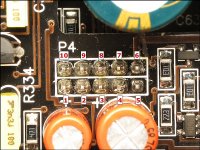
Post the DC voltage on the 10 pin connector. Use the numbering scheme shown on the attached image (different amp). Pin 1: Pin 2: Pin 3: Pin 4: Pin 5: Pin 6: Pin 7: Pin 8: Pin 9: Pin 10:
M mike49504 Member Joined 2006 2011-02-13 1:43 am #37 2011-02-13 1:43 am #37 1:0 2:-4.57 3:12.32 4:11.19 5:0 6:13.11 7:0.26 8:0 9:12.78 10:0 R309 and R231 on this board got so hot they unsolderd themselfs from the board ••• More options Share P Perry Babin Member Joined 2003 bcae1.com 2011-02-13 3:24 pm #38 2011-02-13 3:24 pm #38 Double-check the boards to make sure that the headers are not misaligned. What revision is this amp? ••• More options Share M mike49504 Member Joined 2006 2011-02-13 4:59 pm #39 2011-02-13 4:59 pm #39 REV 8 ••• More options Share P Perry Babin Member Joined 2003 bcae1.com 2011-02-15 2:09 am #40 2011-02-15 2:09 am #40 Post the DC voltage on U504 and U505. ••• More options Share Prev 1 2 3 Next First Prev 2 of 3 Go to page Go Next Last Show hidden low quality content Status This old topic is closed. If you want to reopen this topic, contact a moderator using the "Report Post" button. Share: Facebook Twitter Reddit Pinterest Tumblr WhatsApp Email Share Link
1:0 2:-4.57 3:12.32 4:11.19 5:0 6:13.11 7:0.26 8:0 9:12.78 10:0 R309 and R231 on this board got so hot they unsolderd themselfs from the board
P Perry Babin Member Joined 2003 bcae1.com 2011-02-13 3:24 pm #38 2011-02-13 3:24 pm #38 Double-check the boards to make sure that the headers are not misaligned. What revision is this amp? ••• More options Share M mike49504 Member Joined 2006 2011-02-13 4:59 pm #39 2011-02-13 4:59 pm #39 REV 8 ••• More options Share P Perry Babin Member Joined 2003 bcae1.com 2011-02-15 2:09 am #40 2011-02-15 2:09 am #40 Post the DC voltage on U504 and U505. ••• More options Share Prev 1 2 3 Next First Prev 2 of 3 Go to page Go Next Last Show hidden low quality content Status This old topic is closed. If you want to reopen this topic, contact a moderator using the "Report Post" button. Share: Facebook Twitter Reddit Pinterest Tumblr WhatsApp Email Share Link
M mike49504 Member Joined 2006 2011-02-13 4:59 pm #39 2011-02-13 4:59 pm #39 REV 8 ••• More options Share P Perry Babin Member Joined 2003 bcae1.com 2011-02-15 2:09 am #40 2011-02-15 2:09 am #40 Post the DC voltage on U504 and U505. ••• More options Share Prev 1 2 3 Next First Prev 2 of 3 Go to page Go Next Last Show hidden low quality content Status This old topic is closed. If you want to reopen this topic, contact a moderator using the "Report Post" button.
P Perry Babin Member Joined 2003 bcae1.com 2011-02-15 2:09 am #40 2011-02-15 2:09 am #40 Post the DC voltage on U504 and U505. ••• More options Share