Reversing the L/R RCAs does not change the amp's bad right channel output. The audio source is very clean coming from my cell phone through the 1/8 inch jack. During the video my audio source was from my Laptop which is not as clean. Every time my laptop's harddrive clicked so did the PC275.
The buzzing noise is present from any source and input arrangement, and always on the right channel of the amp.
I've picked up a RS Mini Amp but wont be able to start testing until this evening. I get the idea but I dont know exactly where to hook it up to for testing.
The buzzing noise is present from any source and input arrangement, and always on the right channel of the amp.
I've picked up a RS Mini Amp but wont be able to start testing until this evening. I get the idea but I dont know exactly where to hook it up to for testing.
If the right channel makes noise with no RCAs plugged in, start by touching the probes for the mini amp to the center and shield of the RCA jack. Is there noise there?
You'll probably have to set the volume on the mini amp at a very low level to prevent picking up too much background noise. Initially, set the volume on it so that a 0.1v RMS signal from your signal source produces a moderately loud output from the mini amp.
For testing beyond the RCA jacks, you'll need a clean/quiet ground point. Find a trace or solder pad near the LM837 op-amps that has ~0 ohms resistance to the two non-bridging speaker terminals. Solder the shield for the mini amp to that point (near the op-amps).
When you have the shield ground for the mini amp grounded, you can begin testing the outputs of the 3 LM837 op-amps. The corner pins on each op-amp are the output pins.
Do any of those pins produce noise similar to that you hear from the right speaker?
Using the mini amp now.
With RCAs disconnected:
1. I measure no noise with the mini amp touching disconnected RCA jacks.
2. With the mini-Amp shield grounded and the probe touching the terminal outputs while no speakers are connected, the right channel is making a variable whistling noise sorta like tuning into old Ham or over the air transmission. The left channel is clean.
With RCAs connected
Testing with the RCA jacks connected and playing a 125hz sin wave yields bad right and good left speaker teminal outputs. The right side seems noisy all the way down the transistor line from Q45 through Q52.
For the OpAmps, I just cant seem to find a pin measuring closest to ~0 ohms from the unbridged terminals to any of eaches' 14 pins. I skipped that part and just ran the mini from general chassis ground and found nothing unclean sounding. I think I need a little more help with this step.
Heres some more videos of the experience thus for anyone interested in looking.
PPC PC275 :: VID_20101018_171724.mp4 video by unclemeat2010 - Photobucket
PPC PC275 :: VID_20101018_171949.mp4 video by unclemeat2010 - Photobucket
Thanks and best regards
Last edited:
The ground near the op-amps won't be connected to the output of the op-amps. You'll connect the shield ground of the mini amp to the ground near the op-amps. When looking for noise, you need to have the cleanest ground for the components being tested. You could use the non-bridging speaker terminals as the ground for the mini amp but you may pick up noise that's not related to the problem.
You'll touch the center conductor for the mini amp to the output pins of the op-amps.
The mini amp IC can't take significant input voltage. Touching it to the speaker outputs or to the output transistors could cause it to fail. Inserting a 10uf 100v capacitor in series with the input of the mini amp will help protect it from DC but not from high voltage AC.
I realized the mini amp is a very simple tool when I put the 9v into it. I'll take more care about hooking it up to high voltage in the future. The I'll make sure my DVM is only measuring .1v AC at the speaker out from now on. Thats enough to make it a noisy reading.
I did what you said; I tested the opAmp outputs using each of the unbridged speaker terminals. The left channel is clean on all opAmp outputs. The right channel is dirty on all opAmp outputs.
Hmm. I may be jumping to conclusions but are the opAmps after the gain controls? Is the noise coming from somewhere higher upstream than the input signal?
There is at least one op-amp (probably 2) for each channel is before the gain control. There are 4 op-amps per LM837.
It's very strange that you have noise on all of the right channel op-amps but none on the input RCA jacks. There are only a few components between the RCA jacks and the first op-amps for the right channel. Are there any components that appear broken, have deep scratches or appear to have been stressed in any way. Any parts causing problems like this would probably have to be between the RCA jacks and the op-amp closest to the RCA jacks.
It's very strange that you have noise on all of the right channel op-amps but none on the input RCA jacks. There are only a few components between the RCA jacks and the first op-amps for the right channel. Are there any components that appear broken, have deep scratches or appear to have been stressed in any way. Any parts causing problems like this would probably have to be between the RCA jacks and the op-amp closest to the RCA jacks.
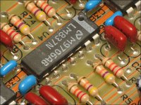
Theres nothing obvious. All the resisters in this picture appear to check out OK.
I dont know what and how to test the 8 pins-in-a-line components. SMT B 103G is stamped on them.
Maybe its time for me to pull the board out of the chassis.
R14 is my dirty-resolder. Its the soldering iron, not me.

I dont know what and how to test the 8 pins-in-a-line components. SMT B 103G is stamped on them.
Maybe its time for me to pull the board out of the chassis.
R14 is my dirty-resolder. Its the soldering iron, not me.
When you need to reinstall the board, it's important that no debris or hardened heatsink compound gets under the transistors. The clamps won't apply enough pressure to displace hardened heatsink compound so the transistors can overheat and fail very easily. After you repair it, you'll need to remove all of the old compound and replace it.
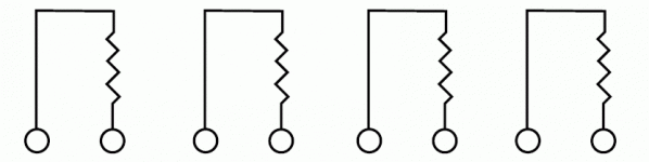
The resistor networks are likely 4 individual, isolated resistors configured as in the attached image. They would be difficult to check in the board. They are 10k ohms each and other, parallel components would likely skew any readings.
The resistor networks are likely 4 individual, isolated resistors configured as in the attached image. They would be difficult to check in the board. They are 10k ohms each and other, parallel components would likely skew any readings.
Attachments
Hey. Im not sure what I just did, but I sure did something positive. I'm still testing, but I think the right channel just cleared up a bunch. I hooked up just the PCB outside of the heat sync and gave it a try. The mini amp is only picking up about 10% of the noise it was before and nowhere even close to how my home-videos did.
Things I done did:
1. I let half the smoke out of U1 (not even kidding) by accident. U1 sparked but the silicon must still be inside cause she look A-OK. LOL she still works!
2. Without power (sigh) I lightly scraped the back of the pcb between a lot of the resistors and capacitors in close proximity to the RCAs and first opAmp.
I'm gonna pull the plug on all this testing and get to town on lightly re-flowing about 1/4 of the board near the opamps and see how that works out. It would be somehting if I dont have to buy any components after all...
It's virtually impossible for a solder connection to be bad on a double-sided board unless the connection has overheated. Resoldering multiple connections for no reason is likely to cause more problems than it solves.
Is any of the 3 op-amps getting hotter than the others?
If any smoke came out of any op-amp, it needs to be replaced. Don't try desoldering each leg to remove the op-amp all at once. Cut all of the legs as shown in the attached photo, remove the body of the op-amp and desolder each leg from the top. Do NOT make contact with the solder pads on the top. Heat only the leg. Remove each one individually. If you don't do it this way, you're likely to badly damage the board.
Attachments
Nope. No smoke came out of an opAmp. Too late - I very carefully resoldered the resister clusters, caps, and as many resisteres in and aound the opAmps. I used caution around resoldering any of the first opAmp pins - I used a alagator clip as a heatsync attached near the silicon.
I use a butan soldering iron which is good... and bad... Good because it doesnt make or cause any electronic interferance, and bad because the heat is a little hard to manage for some. I've been using that thing for about 10 years and am pretty decent with it. Everything I want and have time for is now re-soldered.
The PCB by itself sounds clean on both channels now. Time to put it back in the chassis!
OK looks like its fixed. For now I'm going to chalk it up as a bad connection on the PCB.
Now I wish I only watched my hands. While testing I let the remote turn-on lead move and short out the left non-bridged speaker terminal. Q10 (2N6491) went up in smoke and I had to clip it off the board due to it becoming a shorted. Also the resister (R13) right near it now reads .6 ohms and its a .22
Both channels still play noise-free. At this point even with one fet short I'm gonna put it back together if you think thats alright.
For the order list, should I replace all or just the one?
Q10 (fried / removed), Q9, Q8, Q50, Q51 and Q52 are all the same part 2N6491.
Since now Ive gotta order something, should I order anything else like Caps or opAmps?
Last edited:
At the very least, you need to replace all of the 6491s in that channel and all of the emitter resistors for the 6491s. I'd also suggest that you replace all of the 6488s in that channel. If the amp is using MPSA06s and MPSA56s for drivers, I'd suggest that you order several of those also. Order 3 LM837s also, in case they need to be replaced.
When you power it up again, try pushing on various points on the board and components (capacitors, switches, potentiometers...) to see if you can make the noise change when you push on them.
Also check the insulators in the amp. If there is any defect in the insulator or a sliver of metal that's cutting through the insulator, the insulator will need to be replaced.
Good deal, I'll get to ordering some stuff later today.
Last night I went back and checked the opAmps. This time I checked them with the mini amp's shield connected to a pad in close proximity to the opAmps. I found about half the opAmp outputs sound good, and another half are coming through with similar noise as the right speaker terminal. No one opamp came up as all good or all bad which leads me to believe the opamps ICs must be shared between both channels, and I'm also guessing some of the opAmp outputs must be in parallel with other outputs. Does this sound like a bad output on one of the opAmps?
Replace the opAmps? SHoud I get some BurBrowns? This amp runs front speakers.
- Status
- This old topic is closed. If you want to reopen this topic, contact a moderator using the "Report Post" button.
- Home
- General Interest
- Car Audio
- PPI Powerclas PC2150 and PC275 need repair ideas