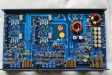
Hi, I have a Soundstream ref 414s which is showing the diagnostic led on. I have stripped the amp down and have found 2 areas of interest which could be the source of the problem.
I have marked the pics with arrows to show visible damage,
Any suggestions on what has caused damage and how to repair are appreciated.
I can easily pull and replace any components but Im not sure where to start.
Also note on one of the pics there is a bad repair to a burnt track which I have indicated with a yellow arrow. Thanks
Attachments
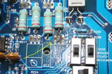
Looks like one or more of the outputs in that channel have gone south on you and past DC to the output which may or may not have damaged the trace that appears to have been repaired.
Most likely the SIP driver card is also damaged for that channel. So a guesstimate would be to rebuild the entire channel < without any testing or DC voltages guess >
The SIP card can be repaired in most cases since the only source I knew of has stopped selling them, luckily I stocked up on some of the odd ball parts before he stopped.
Also Stewart electronics can repair this amp, and since he designed and built them for SoundStream he is a good bet on a proper repair by someone else. He is open for business here in NorCal. PM me if you need the contact info, I have his email address if you like. I also have the parts and info but am backed up over a month myself, so I am not a timely option at this point.
Would you advise changing all 4 TIP102's and TIP107's on the blown channel?
Can I use alternative devices?
Thanks
Yes of course please do so, and I would change all of them as sets. But this will most likely still not complete the repair of this order. And no I know of no replacements other then original parts TIP102 and TIP107.
The big ceramic resistors like to go open or raise from their original values on a failure like this, they must be checked for value.
Also the large vertical card located to the left of these bad outputs will most likely still be damaged. These get damaged all across the board from the input diff pairs to the drivers on the corners and sometimes burnt resistors here also.
")
Once the outputs are replaced a simple DC offset across the speaker terminals will tell the tale of weather you need to look further and possibly where to look also.
Hi again, this morning I did a simple test on the amp before pulling any components and it appears the amp does NOT show the diagnostic led as I was led to believe by previous owner, it simply keeps blowing the fuses?
Any ideas???
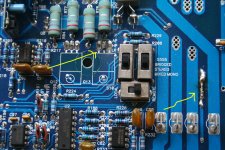
Check the rectifier diodes on the secondary of the supply and if they are OK then check the mosfets on the 12 volt side of the supply for failures. Just ohm them out with your meter. They will read dead short usually if bad. careful when measuring the diodes depending on how you ohm the leads you will read the secondary of the power transformer and it may confuse you as it will look like a short...Let me know what you find...
Thanks 1moreamp, can you point the diode and mosfets out on the pictures I posted? as I don't want to get this wrong thanks
Just look to the right side of picture one above and look above the left toroid and there are the rectifier diodes which short out fairly often. Then look to the far right top corner and you will see the power transformer toroid, just below it in two rows are the mosfets for the power supply. they are banks 3 each on either side of the capacitors all lined up pretty in a row.
Ohm all of these devices out with a meter. Any of them reading a shorted I.E. less then 30 ohms are suspect.
remember what i said about the rectifiers and read them with the caveat that they sit across the secondary of the power transformer and you may be reading the windings resistance not the diodes continuity. This often confuses the average novice repair person. I myself have had to remove certain FED diode pairs to make sure they were not defective myself. each of the four diode packages has two diodes in each TO-220 package. So try to measure from the center leg out to the right leg and then center to the left leg.
If this amp has FED fets often marked with green marker on the tabs, these may have to be removed carefully to avoid breaking the leads to test them properly and not get the transformer windings in the readings. its been so long since I saw one of these I am not sure if it had the FED dual diodes or not. The green marker on the tabs is dead give away that it is them. SS used Red and Blue for the other diodes they used back then.
The above will only test the power supply and if nothing is indicated then your likely will need to ohm out all the rest of the output transistors in each channel looking for a possible dead short on the supply, which will blow the fuse every time the amp gets turned on..
Last edited:
- Status
- This old topic is closed. If you want to reopen this topic, contact a moderator using the "Report Post" button.
- Home
- General Interest
- Car Audio
- Soundstream Ref 414s repair pics