Working on an Orion 222sx amplifier and I'm wondering if the PWM waveform on each "channel" of the TL594 IC should be pretty much identical but simply out of phase... this is what I'm looking at right now
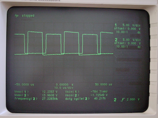
you can see that the signals don't match, the 594 isn't currently driving any transistors only a resistive load because I disconnected the two resistors that lead to the bases of the drivers. Ch1. has a close to ideal square wave where as Ch2 doesn't. Right now I am assuming that the TL594 IC is bad.
you can see that the signals don't match, the 594 isn't currently driving any transistors only a resistive load because I disconnected the two resistors that lead to the bases of the drivers. Ch1. has a close to ideal square wave where as Ch2 doesn't. Right now I am assuming that the TL594 IC is bad.
well you were right, I put my probes on the same spot and the waveforms were different, tried a different probe and now they match up. I was trusting that my equipment was working correctly, guess it wasn't. I'll post updates as I keep going through this thing. Thanks.
btw: I was suspecting that the 594 had problems because two of the MPSA56 drivers had nearly shorted to ground.
btw: I was suspecting that the 594 had problems because two of the MPSA56 drivers had nearly shorted to ground.
Last edited:
I've pulled the SF163C and SF163A rectifiers to find them somewhat leaky, the worst is about 600k ohms with one of the diodes reverse biased. With the rectifiers removed the power supply initially seems to comes up fine until it nears its maximum duty cycle then what seems to be the toroid begins to make a buzzing sound and the power supply draws excessive current. Initial problems with this amp was that it would draw excessive current on power up.
Could the power supply be acting up without feedback from a power rail or is there likely something else wrong?
Could the power supply be acting up without feedback from a power rail or is there likely something else wrong?
yes, I could see the duty cycle increasing on my scope. I threw everything back together and the power supply appears to come up. The rail feedback to pin 1 of the error amp causes the PWM to be shutdown intermittently and the duty cycle to be very short (~500 ns pulse @ 27 kHz iirc). The rail feedback to pin 1 is through a zener and a voltage divider network to ground. There is a voltage divider network from pin 3 to pin 2 to ground. I checked the math and it seems that it is working correctly. With the 15V zener the rail voltages are just above 17V.
I found that the 7912 regulators for the preamp section are bad. I pulled them and tested them out of circuit and they are very much faulty. I'll have to get more parts and then see what happens from there.
I found that the 7912 regulators for the preamp section are bad. I pulled them and tested them out of circuit and they are very much faulty. I'll have to get more parts and then see what happens from there.
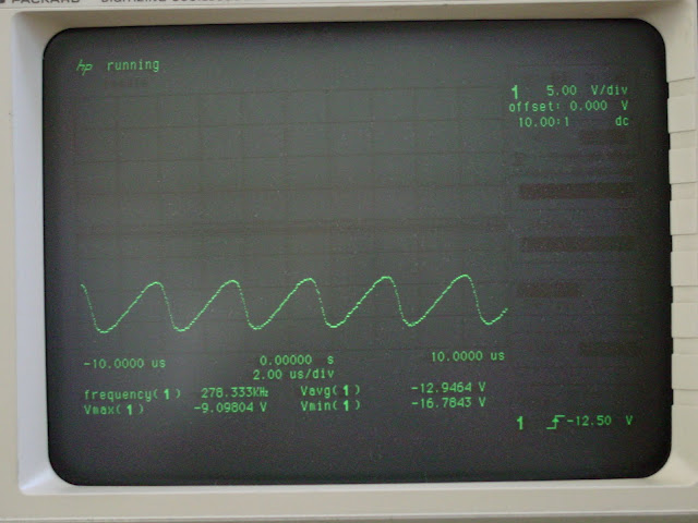
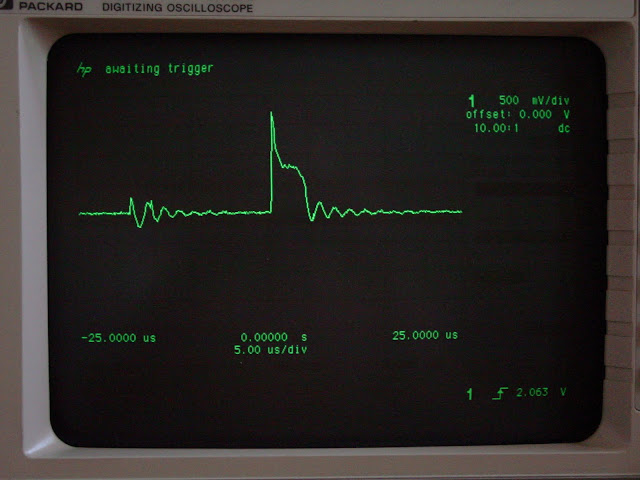
The power supply uses D44H11 BJTs for switching, here is the view of the emitter output from the TL594.
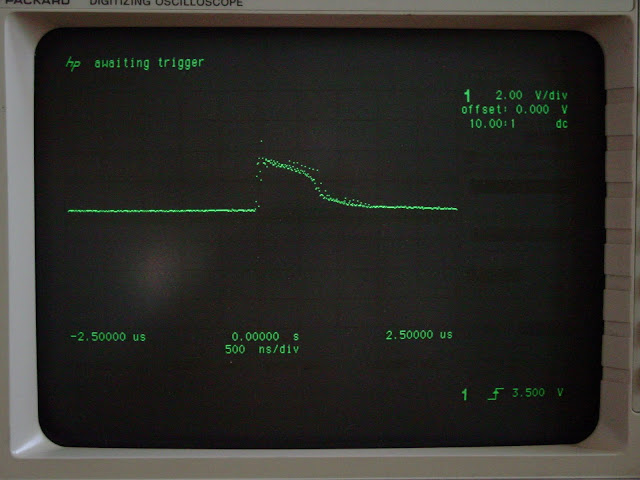
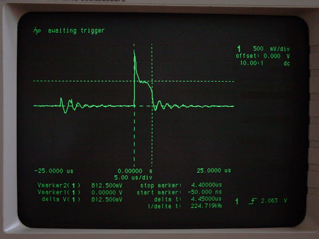
here is the view at the base of the switching D44H11:
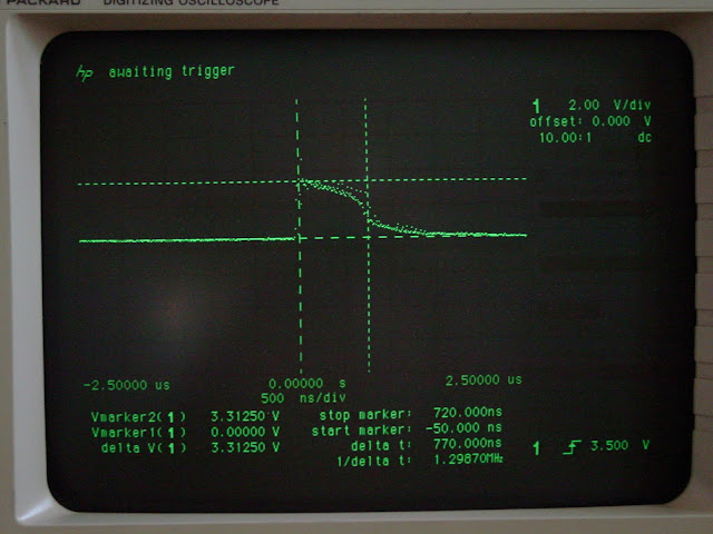
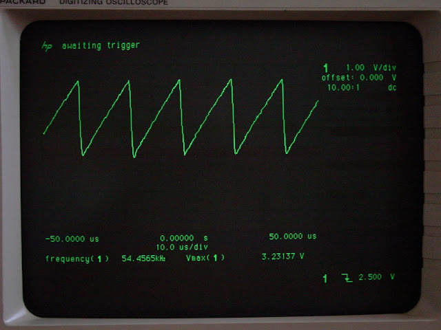
and last here's the triangle from the TL594
the pulse width does not seem to stay constant, like I've said before it seems the rail voltage feedback is shutting off the PWM signal. Just to recap I've already replaced the MPSA56 drivers (low resistance) and the 2.7 ohm emitter resistors to ground (opened up) The D40D8 drivers checked ok on diode check and the D44H11s diode check ok as well. There is ~17.5V rail voltage and the amp does not draw excessive current right now (faulty -12V regulators were removed and OPAMP preamp section is not currently connected to the discrete power amplifier section. I have extra TL594 ICs laying around, should I pop in a new IC to see if the signal cleans up?
would you happen to know what the rail capacitor values are suppose to be for this amplifier, I think someone may have changed out the caps at one point and I want to be sure that they are the correct value, 2200uF 25V.
here is the view at the base of the switching D44H11:
and last here's the triangle from the TL594
the pulse width does not seem to stay constant, like I've said before it seems the rail voltage feedback is shutting off the PWM signal. Just to recap I've already replaced the MPSA56 drivers (low resistance) and the 2.7 ohm emitter resistors to ground (opened up) The D40D8 drivers checked ok on diode check and the D44H11s diode check ok as well. There is ~17.5V rail voltage and the amp does not draw excessive current right now (faulty -12V regulators were removed and OPAMP preamp section is not currently connected to the discrete power amplifier section. I have extra TL594 ICs laying around, should I pop in a new IC to see if the signal cleans up?
would you happen to know what the rail capacitor values are suppose to be for this amplifier, I think someone may have changed out the caps at one point and I want to be sure that they are the correct value, 2200uF 25V.
Last edited:
I don't know what the original capacitors were. I don't see any problem with the 2200uf caps.
I would expect the drive signal on pins 9 and 10 to be square across the top but I don't remember ever checking it on this type of supply. Orion used it for a very limited number of amps and haven't seen many.
What is currently the problem with the amp? I think you may need to wait until you have the rest of the replacement parts before you can determine if there are any real problems.
Initially, the problem was that the amp would power up and after a couple seconds draw excessive current. I found that there was a wild voltage swing throughout the preamp section and discrete amplifier section. I put in a used 7912 regulator to power the preamp section and it had near the same output as the old regulator:
I found that the 470 uF filter caps for the preamp rails were leaking at their bottoms and no where near 470 uF. I placed 220 uF caps on the rails for testing and now the negative preamp rail is steady near -12V, I'm guessing a lack of output capacitance was causing the -12V regulator to be unstable. The huge voltage swing on the -12V rail seems to be what was causing the opamp outputs to swing wildly because now they seem to be stable as well. The preamp section is still currently not connected to the discrete amplifier section but I think I am near getting this amp into a functioning state. So that is the current state of things, hopefully when the preamp is connected to the discrete amp everything will work.
I found that the 470 uF filter caps for the preamp rails were leaking at their bottoms and no where near 470 uF. I placed 220 uF caps on the rails for testing and now the negative preamp rail is steady near -12V, I'm guessing a lack of output capacitance was causing the -12V regulator to be unstable. The huge voltage swing on the -12V rail seems to be what was causing the opamp outputs to swing wildly because now they seem to be stable as well. The preamp section is still currently not connected to the discrete amplifier section but I think I am near getting this amp into a functioning state. So that is the current state of things, hopefully when the preamp is connected to the discrete amp everything will work.
Last edited:
Some short in the audio output stage
Hi,
I've been working with car audio AMPs for a long time. Looking at your problem it seems to me that you have some output stage mosfet or bipolar in short circuit.
Try to unplug the power supply and measure resistance in the output of the transistors. I assume that someone may be bad.
Since the circuit is generating DC to the other side of the toroid this is what may be happening...
Just to update the thread, I reconnected the preamp to the discrete amplifier and everything seems to be working good. Haven't ordered new parts to finish up the amplifier yet but I will do that soon. Still wondering if the waveform at the base of the D44H11 switching transistors is fine. Maybe if someone has an orion 222 sx lying around they could chime in. Thanks for your help Perry, it is very much appreciated ")
- Status
- This old topic is closed. If you want to reopen this topic, contact a moderator using the "Report Post" button.
- Home
- General Interest
- Car Audio
- question about TL594 PWM signals