Current behavior:
turns on, runs for 10 or so seconds with distortion. Towards the end of those ten seconds i hear a faint very high pitched whine which sounds to be above 10khz. Then it shuts down for around 2 seconds, turns back on, and the cycle starts over. I suppose the whine is coming from one of the toroids in the power supply area but I have not tracked it down. When it is whining it seems like it is drawing a lot of current. I have not measured how much but it is enough to draw down my 12v power supply voltage a bit.
Any pointers would be appreciated.
All channels?
These amps are VERY sensitive to voltage drop and dips that are so short that they don't show up on a multimeter will cause it to shut down. Are you sure that this isn't the problem?
All channels were out when it was in the car. I took it in, put it on the bench, and it seems to be doing the same thing there (the repetitive turning off). It is possible both the car battery and bench power supply have problems but the JL 300/4 I swapped into the car is not having a problem and neither have other amps I have run off the bench PS so I think that is unlikely.
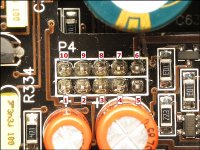
Post the voltage on all 10 pins of the connector shown in the photo (view full size to read numbering scheme).
Post one set before it whines and one set after it whines.
Before
Pin 1:
Pin 2:
Pin 3:
Pin 4:
Pin 5:
Pin 6:
Pin 7:
Pin 8:
Pin 9:
Pin 10:
After
Pin 1:
Pin 2:
Pin 3:
Pin 4:
Pin 5:
Pin 6:
Pin 7:
Pin 8:
Pin 9:
Pin 10:
Post one set before it whines and one set after it whines.
Before
Pin 1:
Pin 2:
Pin 3:
Pin 4:
Pin 5:
Pin 6:
Pin 7:
Pin 8:
Pin 9:
Pin 10:
After
Pin 1:
Pin 2:
Pin 3:
Pin 4:
Pin 5:
Pin 6:
Pin 7:
Pin 8:
Pin 9:
Pin 10:
Attachments
Post the voltage on all 10 pins of the connector shown in the photo (view full size to read numbering scheme).
I do not see a connector like that on my amp. Where would it be located? The caption on that picture says it is for a 500/1 and I have a 500/5 so that may be the issue...
Thanks,
Matt
I didn't have a photo for the 500/5 with the numbers on it. Your amp has the same connector. It's labeled P800 on the board and it's near the power/ground terminals.
OK here are the measurements. I am taking pin 1 as the one closest to the power connector and working counterclockwise. The second numbers are when it whines.
1. as high as 18v, most of the time 11, falling to .5, then briefly back to 18
2. 45mv down to -20V
3. 11.3 dropping to 9.5
4. 11.4 dropping to 9.5
5 45mv rising to 2
6. 44mv up to 2v
7. 11.4v falling to 10
8. 12v falling to 10.6
9. 5v rising to 5.7
10. 12v falling to 9.6
Are they numbered like those in the photo?
If not, repost them as they are numbered on the photo.
Well, it is not the same board as the one shown in your picture so I don't see how to compare. I have included a picture I took. What I am calling pin 1 is the one in the top left.
Attachments
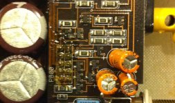
Both boards have orange caps and both have large caps adjacent on the man board.
OK, then with the large and orange caps oriented the same way, gives:
1. 44mv up to 2v
2. 11.4v falling to 10
3. 12v falling to 10.6
4. 5v rising to 5.7
6. 12v falling to 9.6
6. as high as 18v, most of the time 11, falling to .5, then briefly back to 18
7. 45mv down to -20V
8. 11.3 dropping to 9.5
9. 11.4 dropping to 9.5
10. 45mv rising to 2
Thanks,
Matt
Where was the black meter probe?
What is the DC voltage across the B+ and ground terminals of the amp when it's trying to power up (highest and lowest)?
the black probe is on the negative supply terminal
The DC supply voltage ranges from 12.3 to 11.7
Thanks,
Matt
Pins 1 and 10 are directly connected to ground. They should have remained VERY near 0v if you had your black probe on the ground terminal of the amp. Confirm that you have ~0 ohm between the ground terminal and pins 1 and 10 of the 10 pin connector.
Can you re-check 6 and 7.
Pin 6 is driven from the B+ terminal and if pin 5 didn't go near 18v, it's virtually impossible for 6 to reach 18v.
Pin 7 is driven from the negative regulated supply and shouldn't be greater than negative 15. -20 is well out of tolerance.
Make absolutely sure that you have a good connection between the black terminal and the ground terminal.
Pins 1 and 10 are directly connected to ground. They should have remained VERY near 0v if you had your black probe on the ground terminal of the amp. Confirm that you have ~0 ohm between the ground terminal and pins 1 and 10 of the 10 pin connector.
Can you re-check 6 and 7.
Pin 6 is driven from the B+ terminal and if pin 5 didn't go near 18v, it's virtually impossible for 6 to reach 18v.
Pin 7 is driven from the negative regulated supply and shouldn't be greater than negative 15. -20 is well out of tolerance.
Make absolutely sure that you have a good connection between the black terminal and the ground terminal.
I checked the resistance on 1 and 10 and they are both 0.4 ohms. I am not sure what the peak voltage I am seeing on 1 and 10 is. The voltage measurements were moving around so fast on the multimeter at the end of the whine that I decided to dig out my scope.
Results:
1 and 10 seem to peak around 500mV and if they ever go higher, I can't see it on my scope (old analog model)
6 is around 11.3V (sometimes around 0)
7 is around -13V (also sometimes around 0)
the extreme values I reported before for 6 and 7 are not visible on the scope though I still see them on the multimeter. My guess is that the multimeter gives bogus values before it settles. Sorry I gave you bad data.
-Thanks
I don't think I'm going to be able to help on this one. The amp I have here that I could use as a guide will be going out tomorrow. The meter you have wasn't working properly so you couldn't give the voltages I needed (the two lists I asked for early in the thread). At this point, I think you're going to have to pull the heatsink and begin checking all of the outputs. One or more may be shorted.
- Status
- This old topic is closed. If you want to reopen this topic, contact a moderator using the "Report Post" button.
- Home
- General Interest
- Car Audio
- help repairing JL 500/5