Hello
Autostudio is not so well known finnish brand, but I have heard that they are copies of Kenwood.
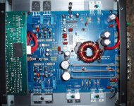
Picture of the insides attached:
If this really is copy of some Kenwood model then it would be great to know which one, because I think schematic for Kenwood is much more easier to find than for Autostudio.
The problem:
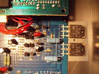
Wiring and all that was OK. So I started to look around on the inside. Everything looked good, but on the output transistor resistance between BE, BC and CE were all 0 ohms. That transistor is blown, and there are npn and pnp transistors working together, so I need to change them both.
(Aluminium thing that presses them to heatsink was there, I removed it to check which transistors are used.)
Found a local store which has both of those transistors in stock and also the thermal tape thing.
The amplifier belongs to a friend of mine who got it for free, if he is willing to invest some money in the amp I would like to change those.
I understood that if I replace the 30 A fuse with a smaller one (10 A?) then I can test the amplifier without blowing transistors again if there are other problems as well.
If one channel consists of 4 output transistors and you remove 2 then it is possible to turn on the amplifier without damaging it. What about if there are only two and I remove those and try to power up the amplifier to see if the protection light goes on?
How high is the probability that only output transistors are shorted and evrything else is intact?
Thanks in advance for answers and other tips for noob are also welcome.
Autostudio is not so well known finnish brand, but I have heard that they are copies of Kenwood.
Picture of the insides attached:
If this really is copy of some Kenwood model then it would be great to know which one, because I think schematic for Kenwood is much more easier to find than for Autostudio.
The problem:
Wiring and all that was OK. So I started to look around on the inside. Everything looked good, but on the output transistor resistance between BE, BC and CE were all 0 ohms. That transistor is blown, and there are npn and pnp transistors working together, so I need to change them both.
(Aluminium thing that presses them to heatsink was there, I removed it to check which transistors are used.)
Found a local store which has both of those transistors in stock and also the thermal tape thing.
The amplifier belongs to a friend of mine who got it for free, if he is willing to invest some money in the amp I would like to change those.
I understood that if I replace the 30 A fuse with a smaller one (10 A?) then I can test the amplifier without blowing transistors again if there are other problems as well.
If one channel consists of 4 output transistors and you remove 2 then it is possible to turn on the amplifier without damaging it. What about if there are only two and I remove those and try to power up the amplifier to see if the protection light goes on?
How high is the probability that only output transistors are shorted and evrything else is intact?
Thanks in advance for answers and other tips for noob are also welcome.
Attachments
Last edited:
It's not likely a copy of a Kenwood. It's more likely to be similar to the Power Acoustik amps. Email me if you want the schematic diagram.
babin_perry@yahoo.com
It's possible that there is no further damage. If you can't find any other defective components, you'll have to replace the ones that you found to be defective.
It's possible to remove the blown outputs (leaving the good ones) to continue troubleshooting but this one has only 2 per channel so if you remove them from the blown channel, only one channel will produce audio.
The 10 amp fuse can only protect the semiconductors if they are all clamped tightly to the heatsink. The chance of damaging the clamped semiconductors with the 10 amp fuse inline is minimal but it will not entirely remove the risk of component failure.
I understood that if I replace the 30 A fuse with a smaller one (10 A?) then I can test the amplifier without blowing transistors again if there are other problems as well.
For testing, you can put a 12V/50W light bulb in series with power supply. It will protect your amp from blowing.
OK, the owner decided to give it a try.
Thanks for quick answers.
What is the safest way to proceed?
Other transistors in the supply seemed to be OK, which details are also likely to be defected?
Should I remove the blown transistors, try if the amp still goes to protection mode?
Or just replace them and see what happens with a smaller fuse in place.
If I test the amp and clamp the transistors do i need to install the thermal tape at once or can I do it afterwards?
The transistors MUST be insulated from the heatsink. You can reuse the original insulators, especially for testing.
Removing the outputs from the defective channel shouldn't cause any problems. With those removed, the amp should power up and produce audio from the remaining channel.
The driver transistors and the base resistors may be damaged. You can check the resistors in the board after removing the transistors. The drivers should be removed for definitive readings.
It's also possible that one of the large emitter resistors has been damaged. Confirm that they're within tolerance. Since it's unlikely that your meter goes to 0 ohms when you touch the probes, touch them before measuring the resistance across the emitter resistors. Then subtract what the meter reads with the probes shorted from the reading you get across the emitter resistors.
Resistance of base resistors on the broken channel was identical to the working channel 220 ohms for 2sa1694 base and 2700 ohms for the other transistor. Colored stripes tell me the same values as well.
Large emitter resistors I could not check because my digital multimeter shows me 0 ohms for both emitter resistors on both channels. They have very small values? Checked the stripes and came to conclusion that they have the value of 0,1 ohms, is that correct?
By driver transistors you mean transistors in power supply? If yes then those I soldered out yesterday and checked with multimeter and they are OK.
- Status
- This old topic is closed. If you want to reopen this topic, contact a moderator using the "Report Post" button.
- Home
- General Interest
- Car Audio
- Autostudio e-80.2 amplifier in protection mode