Hi guys,
New member here, first of just to say this looks to be a great forum with some very knowledgeable people. Unfortunately I have a problem with my rockford fosgate punch 400x4.
I had this amplifier connected in 4 channel stereo mode, it initially had a problem where one of the front channels would sound distorted, I swapped the RCA's and the output channels round and bizarrely the problem was solved.
Now since recently disconnecting the amplifier and re installing it I can now connect the front channels up as normal with the red/white rca going in the correct way and can connect the left channel to the left speaker and so on.
But the rear right channel now sounds distorted while the rear left seems to play clear. I swapped the rca's around, changed the rear right speaker and the problem was still there. I then connected the rear right speaker to the rear left channel and the problem was solved and connected the rear left speaker to the rear right channel and that still played a distorted signal.
This seems strange as I have tried to swap the rca/output channels around like last time but the problem is still evident.
I have removed the amp and had a look at the circuit board and all the joints seem to be in good condition. The REM connection also came loose and I have re soldered that in and that works 100%. I don't know what to look for when checking transistors/resistors/FET's and I don't have acess to a scope or a bench.
I have good soldering skill and a multimeter, can anyone please advise what could possibly be the problem and how I can resolve this issue?
Many thanks!")
edit: just to add I also swapped the crossovers from the front and pass through to the rear crossovers and the problem was still there, I also have a spare 60ix from which I can borrow the crossovers from and can swap into the 400x4 if the above was not the correct way to go about this.
New member here, first of just to say this looks to be a great forum with some very knowledgeable people. Unfortunately I have a problem with my rockford fosgate punch 400x4.
I had this amplifier connected in 4 channel stereo mode, it initially had a problem where one of the front channels would sound distorted, I swapped the RCA's and the output channels round and bizarrely the problem was solved.
Now since recently disconnecting the amplifier and re installing it I can now connect the front channels up as normal with the red/white rca going in the correct way and can connect the left channel to the left speaker and so on.
But the rear right channel now sounds distorted while the rear left seems to play clear. I swapped the rca's around, changed the rear right speaker and the problem was still there. I then connected the rear right speaker to the rear left channel and the problem was solved and connected the rear left speaker to the rear right channel and that still played a distorted signal.
This seems strange as I have tried to swap the rca/output channels around like last time but the problem is still evident.
I have removed the amp and had a look at the circuit board and all the joints seem to be in good condition. The REM connection also came loose and I have re soldered that in and that works 100%. I don't know what to look for when checking transistors/resistors/FET's and I don't have acess to a scope or a bench.
I have good soldering skill and a multimeter, can anyone please advise what could possibly be the problem and how I can resolve this issue?
Many thanks!
edit: just to add I also swapped the crossovers from the front and pass through to the rear crossovers and the problem was still there, I also have a spare 60ix from which I can borrow the crossovers from and can swap into the 400x4 if the above was not the correct way to go about this.
Last edited:
Thanks brandes, I have had a look at the rca's and they seem ok to me, also there are no leaking capacitors.
I swapped the crossovers over from my 60ix and the problem is still there so its not that.
After a bit of reading and a youtube guide I have increased my knowledge somewhat.
Using a multimeter I measured the resistance at the speaker terminals (with the multimeter set at 20k ohms):
Rear L: 9.24
Rear R: initially 1.22 but over a period of 1 min it rises to 6.30
Front L: 9.19
Front R: 9.22
Also I checked the transistors on the speaker side of the amp and have drawn the following diagram and below are the relevant readings:
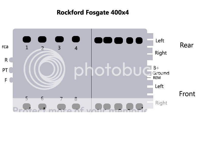
With the mulitmeter set on 2000 ohm I got the following readings:
1: 308
2: 015
3: 306
4: 306
5: 307
6: 305
7: 308
8: 306
So would I be correct in thinking that replacing transistor no2 will increase the resistance at the rear right channel and therefor provide a clean signal?
If so what transistors will I need and would I replace the whole of the top row or the top and bottom?
Many thanks!
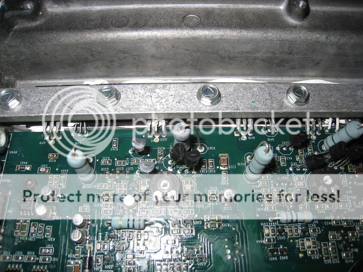
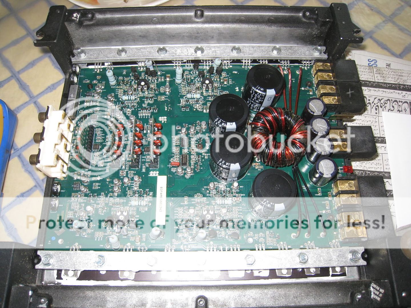
p.s here are some hi res pictures of the amp, can anyone identify any defects?
Possibly some corrosion on the first two channels? Which are the rear channels btw.
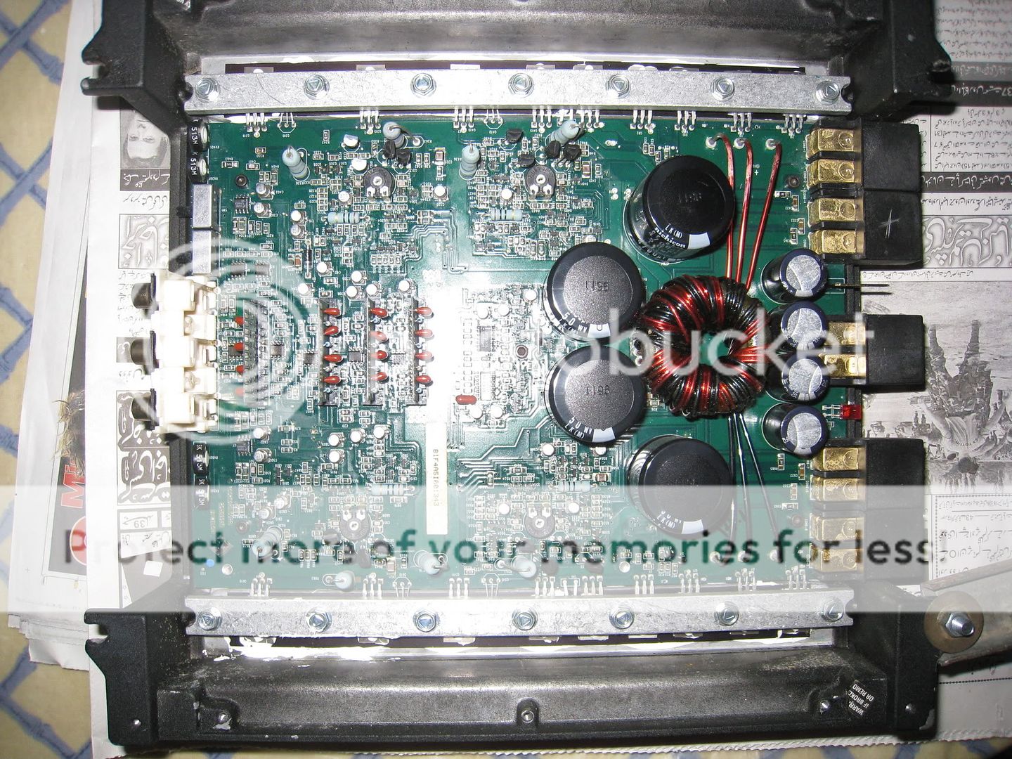
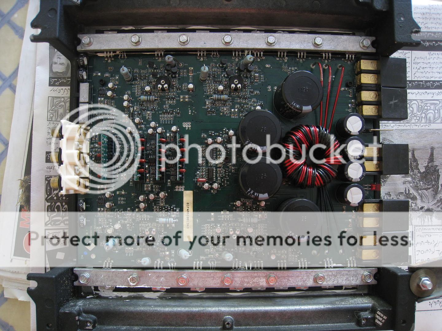
The second transistor in this picture is the one with the low reading ( top left of the amp)
I swapped the crossovers over from my 60ix and the problem is still there so its not that.
After a bit of reading and a youtube guide I have increased my knowledge somewhat.
Using a multimeter I measured the resistance at the speaker terminals (with the multimeter set at 20k ohms):
Rear L: 9.24
Rear R: initially 1.22 but over a period of 1 min it rises to 6.30
Front L: 9.19
Front R: 9.22
Also I checked the transistors on the speaker side of the amp and have drawn the following diagram and below are the relevant readings:
With the mulitmeter set on 2000 ohm I got the following readings:
1: 308
2: 015
3: 306
4: 306
5: 307
6: 305
7: 308
8: 306
So would I be correct in thinking that replacing transistor no2 will increase the resistance at the rear right channel and therefor provide a clean signal?
If so what transistors will I need and would I replace the whole of the top row or the top and bottom?
Many thanks!
p.s here are some hi res pictures of the amp, can anyone identify any defects?
Possibly some corrosion on the first two channels? Which are the rear channels btw.
The second transistor in this picture is the one with the low reading ( top left of the amp)
That's a common reading for failed FETs, especially if they're using BUZxxx transistors. Generally shorted FETs cause excessive current draw but when these FETs short from leg 1-3, they simply cause the output to be distorted. Check the gate resistor on the shorted FET after removing it. Re-check the FET after removing it to confirm that it's shorted.
Hi perry, I know its a totally newbie thing to do but could you please do me a favour and link me to what resistor and and transistor I need to replace R352 and Q321.
The website I wish to use is Welcome to rswww.com
The number currently stamped on Q321 is mps a56 m529
The website I wish to use is Welcome to rswww.com
The number currently stamped on Q321 is mps a56 m529
Vishay | Passives | Resistors | Surface Mount, Fixed | Thick Film - 0805 |CRCW080510R0FKEA
They don't stock the MPSA56 but the following transistor should work.
ON Semiconductor | Semiconductors | Discretes | General Purpose Transistor | PNP Small Signal |MPSA92G
They don't stock the MPSA56 but the following transistor should work.
ON Semiconductor | Semiconductors | Discretes | General Purpose Transistor | PNP Small Signal |MPSA92G
Thanks Perry,
I managed to remove the transistor and it seemed to be working at it should, I had a reading from both the outer legs when the middle was connected to the ground on the multimeter diode test.
When the legs were switched so the positive is on the middle leg there was no reading when the negative was on the outer two legs.
And when both the outer legs were tested against eachother the circuit remained open
So I have placed an order for the resistors and will let you know how I get on
Cheers
Ok guys, sorry for the late update, the supplier of the resistors was out of stock until last week and I have just soldered the replacement resistor in.
The problem still remains, with the resistance on the rear right channel showing 1.22 and steadily increasing.
Anyone able to tell me what to check next?
The problem still remains, with the resistance on the rear right channel showing 1.22 and steadily increasing.
Anyone able to tell me what to check next?
- Status
- This old topic is closed. If you want to reopen this topic, contact a moderator using the "Report Post" button.
- Home
- General Interest
- Car Audio
- RF 400x4, output channel distortion