Hay guys I have a PPI A600 Its not in working condition but I would Like to get it running again when power is connected it arcs good and maybe smoke a little I'm sure it needs a new power supply I took it to my local repair shop and they told me they couldent get parts for it I know the pcb isnt burned anywhere Can some one help. IS this amp even worth fixing???
A car amp that blows the fuse most likely has a shorted transistor or rectifier in the PSU section.
Usually, these parts can be replaced with similar units if the exact replacement is unavailable.
Post the numbers on the devices mounted to the heatsink in the PSU section. Pics are helpful too.
Usually, these parts can be replaced with similar units if the exact replacement is unavailable.
Post the numbers on the devices mounted to the heatsink in the PSU section. Pics are helpful too.
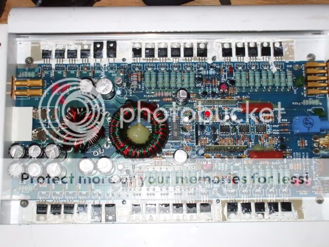
The SMP25n06's are the power supply fets in the amp. They are probably using 100 ohm gate resistors in the amp.
You can replace the power supply fets with IRFZ34's which is a drop in replacement to the SMP parts.
You can also use IRFZ44's in this amp and not have a problem.
I just repaired the same amp and used IRFZ44's and didnt have a problem with them.
Also check the gate resistors in this amp to make sure they are within tolerance. And check the drivers for the power supply fets .
Also wouldnt hurt to check the outputs just to make sure they are not shorted also.
Set your meter to ohm's and check the outputs in this amp you should read nothing near 0 ohm's .
If you are replacing the power supply fets with the z34's or 44's you need to replace them all.
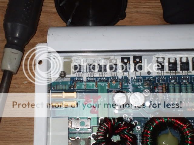
The gate resistors are MR1-MR8.
The output transistors are Q2-Q5, Q8-Q11, Q33-Q36 and Q39-Q42. Check them by measuring the resistance between the legs of each individual transistor leg 1-2, leg 1-3 and leg 2-3. None should read anything near 0 ohms. If you find that 4 read near zero ohms, only one is likely shorted but all 4 must be replaced and the other 4 in the same channel should also be replaced.
I think the 3525 drives the power supply FETs directly but I could be wrong. Measure the resistance from pins 11 and 14 of the 3525 IC to the end of the gate resistors (MR5-6 and MR1-MR3) that are connected by the trace on top of the board. If you read 0 ohms between pin 11 or pin 14 to that end of the resistors, they are driven directly by the IC.
If you want to confirm that the IC is producing the proper output, remove the power supply FETs (all 8 of them) and power up the amp. Measure the DC voltage on the same end of the resistors you used to determine if the IC was directly driving the gate resistors. Do this for all 8 resistors. Place the black meter probe on the amplifier's ground terminal. Place the red meter probe on the point where you need to measure the voltage.
What is the voltage?
Attachments
It's a bit late but... With the power supply transistors out of the circuit, there is very little that can be damaged by overheating. This applies to virtually all amps except the few that have secondary power supplies with transistors that need to be clamped to the heatsink (old MTX class D amps and a few others).
5.2 volts means it's likely working properly.
5.2 volts means it's likely working properly.
- Status
- This old topic is closed. If you want to reopen this topic, contact a moderator using the "Report Post" button.
- Home
- General Interest
- Car Audio
- Ppi a600